Overhead Console Illumination Light Circuit
Circuit diagnosis · Vehicles built Aug 2013 – Jul 2014
Versions by build date: Aug 2013 – Jul 2014 from Aug 2014
DESCRIPTION
The main body ECU controls the center console spot light.WIRING DIAGRAM
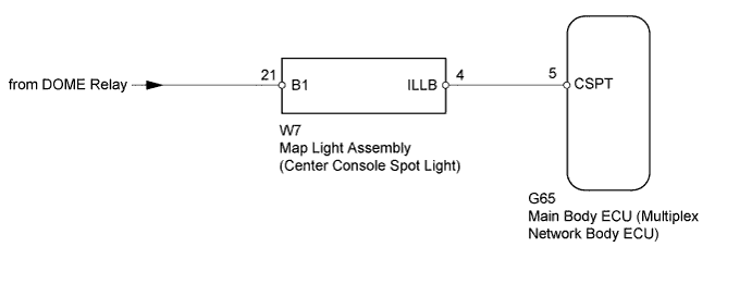

INSPECTION PROCEDURE
- NOTICE:
- Inspect the fuses for circuits related to this system before performing the following inspection procedure.
| 1. PERFORM ACTIVE TEST USING INTELLIGENT TESTER (CENTER CONSOLE SPOT LIGHT) |
 |
Using the intelligent tester, perform the Active Test (Click here).
Main Body
Tester Display
|
Test Part
|
Control Range
|
Diagnostic Note
|
Cent Consol Spot LGT
|
Center console spot light
|
ON/OFF
|
-
|
- OK:
- Center console spot light comes on.
|
NG |
 |
|
|
|
| OK |
|
 |
|
| PROCEED TO NEXT SUSPECTED AREA SHOWN IN PROBLEM SYMPTOMS TABLE (Click here)
|
|
| 2. INSPECT MAP LIGHT ASSEMBLY |
|
- Remove the map light (Click here).
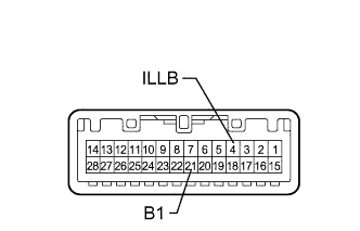
Connect a positive (+) lead from the battery to terminal 21 (B1) and a negative (-) lead to terminal 4 (ILLB).
Check that the center console spot light comes on.
- OK:
- Center console spot light comes on.
|
NG |
 |
|
|
|
| OK |
|
 |
|
| 3. CHECK HARNESS AND CONNECTOR (BATTERY - MAP LIGHT ASSEMBLY) |
|
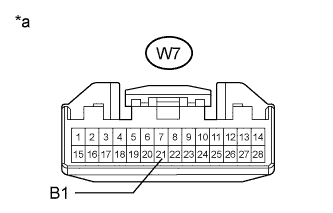
- Disconnect the W7 map light connector.
Measure the voltage according to the value(s) in the table below.
- Standard Voltage:
Tester Connection
|
Condition
|
Specified Condition
|
W7-21 (B1) - Body ground
|
Battery saving control (interior light auto cut function) not operating
|
11 to 14 V
|
Text in Illustration
*a
|
Front view of wire harness connector
(to Map Light Assembly)
|
|
NG |
|
|
| REPAIR OR REPLACE HARNESS OR CONNECTOR |
|
|
| OK |
|
|
|
| 4. CHECK HARNESS AND CONNECTOR (MAP LIGHT ASSEMBLY - MAIN BODY ECU) |
|
Disconnect the W7 map light connector.
Disconnect the G65 main body ECU connector.
Measure the resistance according to the value(s) in the table below.
- Standard Resistance:
Tester Connection
|
Condition
|
Specified Condition
|
W7-4 (ILLB) - G65-5 (CSPT)
|
Always
|
Below 1 Ω
|
W7-4 (ILLB) - Body ground
|
Always
|
10 kΩ or higher
|
|
NG |
|
|
| REPAIR OR REPLACE HARNESS OR CONNECTOR |
|
|
| OK |
|
|
|
| REPLACE MAIN BODY ECU (MULTIPLEX NETWORK BODY ECU) (Click here)
|
|