TERMINALS OF ECU
System information · Vehicles built from Aug 2013
| CHECK FOLD SEAT CONTROL ECU LH |
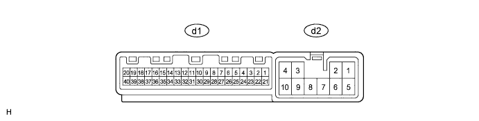

Disconnect the d1 and d2 ECU connectors.
Measure the resistance and voltage according to the value(s) in the table below.
If the result is not as specified, there may be a malfunction on the wire harness side.Terminal No.
(Symbol)
Wiring Color
Terminal Description
Condition
Specified Condition
d2-2 (+B) - d2-9 (GND2)
R - W-B
Power source (Battery)
Always
11 to 14 V
d2-9 (GND2) - Body ground
W-B - Body ground
Ground
Always
Below 1 Ω
d2-10 (GND) - Body ground
W-B - Body ground
Ground
Always
Below 1 Ω
d1-1 (ECUB) - d2-10 (GND)
GR - W-B
Power source (Battery)
Always
11 to 14 V
d1-3 (IG) - d2-9 (GND2)
B - W-B
Power source (IG)
Ignition switch ON
11 to 14 V
Ignition switch off
Below 1 V
d1-6 (P) - Body ground*1
W - Body ground
Park/neutral position switch signal
Ignition switch ON
Shift lever in P
11 to 14 V
Ignition switch ON
Shift lever not in P
Below 1 V
Reconnect the d1 and d2 ECU connectors.
Measure the resistance and voltage according to the value(s) in the table below.
Terminal No.
(Symbol)
Wiring Color
Terminal Description
Condition
Specified Condition
d2-1 (RCL+) - Body ground
B - Body ground
Reclining motor operation signal
Rear power seat switch LH forward
11 to 14 V
d2-5 (RCL-) - Body ground
L - Body ground
Reclining motor operation signal
Rear power seat switch LH backward
11 to 14 V
d2-8 (FLD+) - Body ground
W - Body ground
Cushion motor operation signal
No. 1 or No. 2 fold seat switch LH fold
11 to 14 V
d2-7 (FLD-) - Body ground
B - Body ground
Cushion motor operation signal
No. 1 or No. 2 fold seat switch LH return
11 to 14 V
d1-10 (FLD2) - Body ground
GR - Body ground
No. 1 fold seat switch signal (Fold)
No. 1 fold seat switch LH off
11 to 14 V
No. 1 fold seat switch LH fold
Below 1 V
d1-12 (RCLF) - Body ground
P - Body ground
Reclining forward switch signal
Always
11 to 14 V
Rear power seat switch LH forward
Below 1 V
d1-13 (RCLR) - Body ground
Y - Body ground
Reclining backward switch signal
Always
11 to 14 V
Rear power seat switch LH backward
Below 1 V
d1-14 (RTN2) - Body ground
SB - Body ground
No. 1 fold seat switch signal (Return)
No. 1 fold seat switch LH off
11 to 14 V
No. 1 fold seat switch LH return
Below 1 V
d1-15 (RTRN) - Body ground
L - Body ground
No. 2 fold seat switch signal (Return)
No. 2 fold seat switch LH off
11 to 14 V
No. 2 fold seat switch LH return
Below 1 V
d1-16 (FOLD) - Body ground
V - Body ground
No. 2 fold seat switch signal (Fold)
No. 2 fold seat switch LH off
11 to 14 V
No. 2 fold seat switch LH fold
Below 1 V
d1-17 (SV1) - d1-25 (SG1)
P - R
Folding position sensor power supply
Ignition switch off
Below 1 V
Ignition switch ON
5.5 to 8 V
d1-18 (SFLD) - d1-25 (SG1)
G - R
Folding position sensor signal
Motor operating
Pulse generation
d1-19 (SRCL) - d1-24 (SG2)
LG - W
Reclining position sensor signal
Motor operating
Pulse generation
d1-24 (SG2) - Body ground
W - Body ground
Reclining position sensor ground
Always
Below 1 Ω
d1-25 (SG1) - Body ground
R - Body ground
Folding position sensor ground
Always
Below 1 Ω
d1-37 (SV2) - d1-24 (SG2)
GR - W
Reclining position sensor power supply
Ignition switch off
Below 1 V
Ignition switch ON
5.5 to 8 V
d1-40 (PKB1) - Body ground*2
R - Body ground
Parking brake switch signal
Parking brake switch off
11 to 14 V
Parking brake switch on
Below 1 V
- *1: for Automatic Transmission
- *2: for Manual Transmission
- *1: for Automatic Transmission
| CHECK FOLD SEAT CONTROL ECU RH |
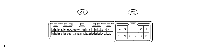
Disconnect the c1 and c2 ECU connectors.
Measure the resistance and voltage according to the value(s) in the table below.
If the result is not as specified, there may be a malfunction on the wire harness side.Terminal No.
(Symbol)
Wiring Color
Terminal Description
Condition
Specified Condition
c2-2 (+B) - c2-9 (GND2)
R - W-B
Power source (Battery)
Always
11 to 14 V
c2-9 (GND2) - Body ground
W-B - Body ground
Ground
Always
Below 1 Ω
c2-10 (GND) - Body ground
W-B - Body ground
Ground
Always
Below 1 Ω
c1-1 (ECUB) - c2-10 (GND)
GR - W-B
Power source (Battery)
Always
11 to 14 V
c1-3 (IG) - c2-9 (GND2)
B - W-B
Power source (IG)
Ignition switch ON
11 to 14 V
Ignition switch off
Below 1 V
c1-6 (P) - Body ground*1
W - Body ground
Park/neutral position switch signal
Ignition switch ON
Shift lever in P
11 to 14 V
Ignition switch ON
Shift lever not in P
Below 1 V
Reconnect the c1 and c2 ECU connectors.
Measure the resistance and voltage according to the value(s) in the table below.
Terminal No.
(Symbol)
Wiring Color
Terminal Description
Condition
Specified Condition
c2-1 (RCL+) - Body ground
B - Body ground
Reclining motor operation signal
Rear power seat switch RH forward
11 to 14 V
c2-5 (RCL-) - Body ground
L - Body ground
Reclining motor operation signal
Rear power seat switch RH backward
11 to 14 V
c2-8 (FLD+) - Body ground
GR - Body ground
Cushion motor operation signal
No. 1 or No. 2 fold seat switch RH fold
11 to 14 V
c2-7 (FLD-) - Body ground
LG - Body ground
Cushion motor operation signal
No. 1 or No. 2 fold seat switch RH return
11 to 14 V
c1-10 (FLD2) - Body ground
GR - Body ground
No. 1 fold seat switch signal (Fold)
No. 1 fold seat switch RH off
11 to 14 V
No. 1 fold seat switch RH fold
Below 1 V
c1-12 (RCLF) - Body ground
P - Body ground
Reclining forward switch signal
Always
11 to 14 V
Rear power seat switch RH forward
Below 1 V
c1-13 (RCLR) - Body ground
Y - Body ground
Reclining backward switch signal
Always
11 to 14 V
Rear power seat switch RH backward
Below 1 V
c1-14 (RTN2) - Body ground
SB - Body ground
No. 1 fold seat switch signal (Return)
No. 1 fold seat switch RH off
11 to 14 V
No. 1 fold seat switch RH return
Below 1 V
c1-15 (RTRN) - Body ground
L - Body ground
No. 2 fold seat switch signal (Return)
No. 2 fold seat switch RH off
11 to 14 V
No. 2 fold seat switch RH return
Below 1 V
c1-16 (FOLD) - Body ground
V - Body ground
No. 2 fold seat switch signal (Fold)
No. 2 fold seat switch RH off
11 to 14 V
No. 2 fold seat switch RH fold
Below 1 V
c1-17 (SV1) - c1-25 (SG1)
P - R
Folding position sensor power supply
Ignition switch off
Below 1 V
Ignition switch ON
5.5 to 8 V
c1-18 (SFLD) - c1-25 (SG1)
G - R
Folding position sensor signal
Motor operating
Pulse generation
c1-19 (SRCL) - c1-24 (SG2)
LG - W
Reclining position sensor signal
Motor operating
Pulse generation
c1-24 (SG2) - Body ground
W - Body ground
Reclining position sensor ground
Always
Below 1 Ω
c1-25 (SG1) - Body ground
R - Body ground
Folding position sensor ground
Always
Below 1 Ω
c1-37 (SV2) - c1-24 (SG2)
GR - W
Reclining position sensor power supply
Ignition switch off
Below 1 V
Ignition switch ON
5.5 to 8 V
c1-40 (PKB1) - Body ground*2
R - Body ground
Parking brake switch signal
Parking brake switch off
11 to 14 V
Parking brake switch on
Below 1 V
- *1: for Automatic Transmission
- *2: for Manual Transmission
- *1: for Automatic Transmission