REMOVAL
Removal / installation · Vehicles built from Aug 2013
| 1. REMOVE CENTER BACK DOOR GARNISH |

Detach the 4 clips and remove the back door center garnish.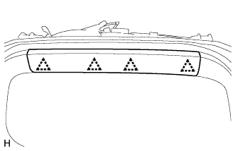

| 2. REMOVE BACK DOOR SIDE GARNISH LH |
Detach the 2 clips and claw and remove the back door side garnish.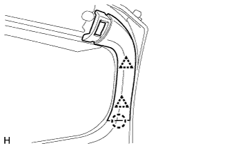
| 3. REMOVE BACK DOOR SIDE GARNISH RH |
Detach the 2 clips and claw and remove the back door side garnish.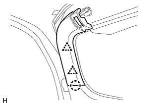
| 4. REMOVE BACK DOOR TRIM COVER |
Remove the back door trim cover as shown in the illustration.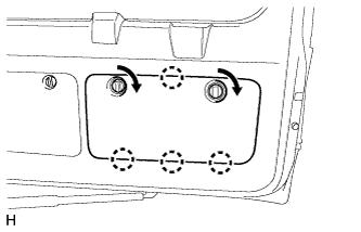
| 5. REMOVE UPPER TOOL BOX PANEL SUB-ASSEMBLY |
Remove the upper tool box panel sub-assembly as shown in the illustration.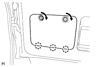
| 6. REMOVE TOOL CASE |
Detach the 2 claws and remove the tool case.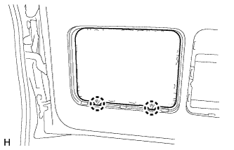
| 7. REMOVE BACK DOOR LOCK COVER (w/o Back Door Tire Carrier, for Standard Type) |
Using moulding remover B, detach the clip and 6 claws and remove the back door lock cover.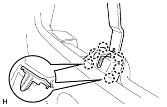
| 8. REMOVE BACK DOOR INSIDE HANDLE BEZEL (w/ Back Door Tire Carrier, for Face to Face Seat Type) |
Remove the screw.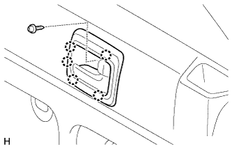
Detach the 5 claws and remove the back door inside handle bezel.
| 9. REMOVE BACK DOOR TRIM PANEL ASSEMBLY |
Detach the claw and remove the cover.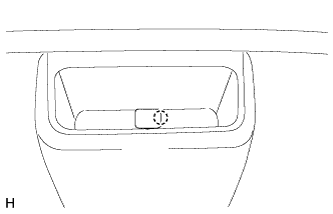
- HINT:
- Tape the screwdriver tip before use.
Remove the screw.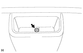
w/o Back Door Tire Carrier:
Remove the bolt.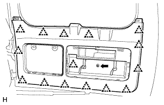
Detach the 15 clips and remove the back door trim panel assembly.
w/ Back Door Tire Carrier:
Remove the bolt.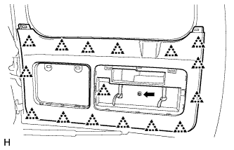
Detach the 16 clips and remove the back door trim panel assembly.
for Face to Face Seat Type:
Remove the screw and bolt.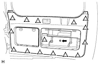
Detach the 15 clips and remove the back door trim panel assembly.
| 10. REMOVE DOOR INSIDE HANDLE SUB-ASSEMBLY (w/ Back Door Tire Carrier, for Face to Face Seat Type) |
Detach the guide.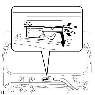
Detach the claws and remove the inside handle sub-assembly.
Disconnect the 2 cables from the inside handle sub-assembly.
| 11. REMOVE BACK DOOR SERVICE HOLE COVER |
Remove the service hole cover.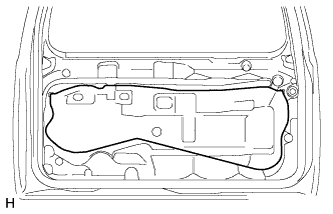
| 12. REMOVE BACK DOOR LOCK ASSEMBLY |
Disconnect the connector.
Using a T30 "TORX" wrench, remove the 3 screws.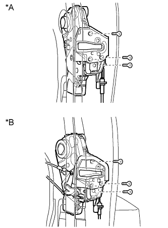
Text in Illustration *A
for Standard Type
*B
w/ Back Door Tire Carrier, for Face to Face Seat Type
- NOTICE:
- Be careful when removing the bolts as the door lock may fall and become damaged.
Disconnect the cable and remover the back door lock assembly.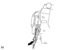
Remove the door lock wiring harness seal from the back door lock assembly.