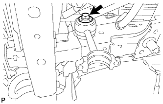
REMOVAL
Removal / installation · Vehicles built from Aug 2013
| 1. REMOVE FRONT WHEEL |
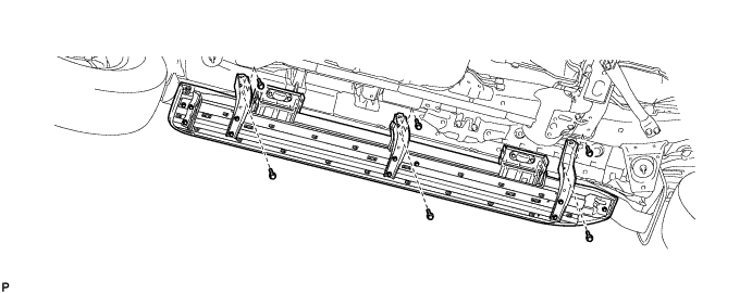
| 2. REMOVE SIDE STEP ASSEMBLY LH (for 5 Door) |

w/ Illumination:
Disconnect the 2 connectors.
Remove the 6 bolts and side step.

| 3. REMOVE STABILIZER CONTROL VALVE PROTECTOR |
Remove the 2 bolts and stabilizer control valve protector.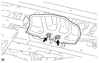
| 4. DRAIN SUSPENSION FLUID |
Loosen the bleeder plug on the stabilizer control with accumulator housing assembly and drain suspension fluid.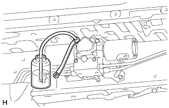
- HINT:
- Drain suspension fluid when performing operations related to the hydraulic circuits.
- Draining suspension fluid decreases suspension fluid pressure.
- Drain suspension fluid when performing operations related to the hydraulic circuits.
Tighten the bleeder plug.
- Torque:
- 8.3 N*m{ 85 kgf*cm , 73 in.*lbf }
| 5. REMOVE LOWER FRONT BUMPER COVER |
Remove the clip, 5 bolts and front bumper cover lower.
| 6. REMOVE NO. 1 ENGINE UNDER COVER SUB-ASSEMBLY |
Remove the 4 bolts.
Unhook the engine under cover from the vehicle body as shown in the illustration.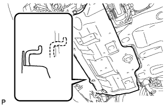
| 7. REMOVE FRONT SUSPENSION MEMBER BRACE SUB-ASSEMBLY |
Remove the 6 bolts and 2 member braces from the front frame assembly.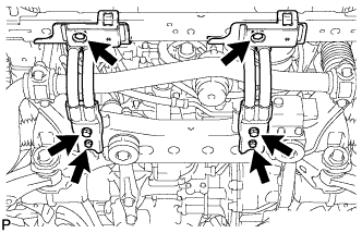
| 8. REMOVE FRONT STABILIZER END BRACKET |
Remove the 4 bolts and 2 brackets from the lower arm.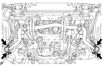
| 9. REMOVE FRONT STABILIZER BAR |
Remove the 4 bolts, 2 front stabilizer lower brackets and front stabilizer bar.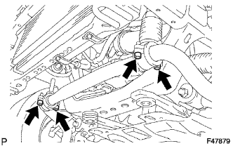
Remove the 2 front stabilizer link bushes and front stabilizer lower bracket bushes from the stabilizer bar front.
| 10. REMOVE FRONT FENDER APRON SEAL LH |
Remove the 7 clips and front apron seal LH.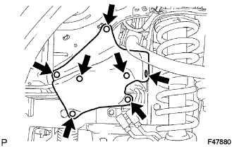
| 11. REMOVE FRAME APRON SEAL BRACKET |
Remove the bolt and bracket.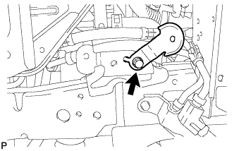
| 12. DISCONNECT NO. 1 FRONT STABILIZER CONTROL TUBE ASSEMBLY |
Using a union nut wrench, disconnect the front stabilizer control tubes.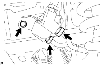
Remove the bolt.
| 13. REMOVE FRONT STABILIZER WITH TUBE CYLINDER ASSEMBLY |
Remove the bolt, nut and front stabilizer with tube cylinder assembly.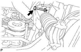
- NOTICE:
- Turn the bolt while holding the nut.
-
Do not loosen or remove the flare nuts labeled A and B in the illustration.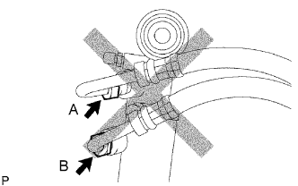
- Do not hold the front stabilizer with tube cylinder assembly by the cylinder boot.
- Turn the bolt while holding the nut.
Remove the 2 bleeder plug caps and bleeder plugs from the front stabilizer with tube cylinder assembly.
| 14. REMOVE FRONT STABILIZER LINK ASSEMBLY RH |
Remove the bolt, spacer and front stabilizer link assembly.