SYSTEM DIAGRAM
System information · Vehicles built from Aug 2013
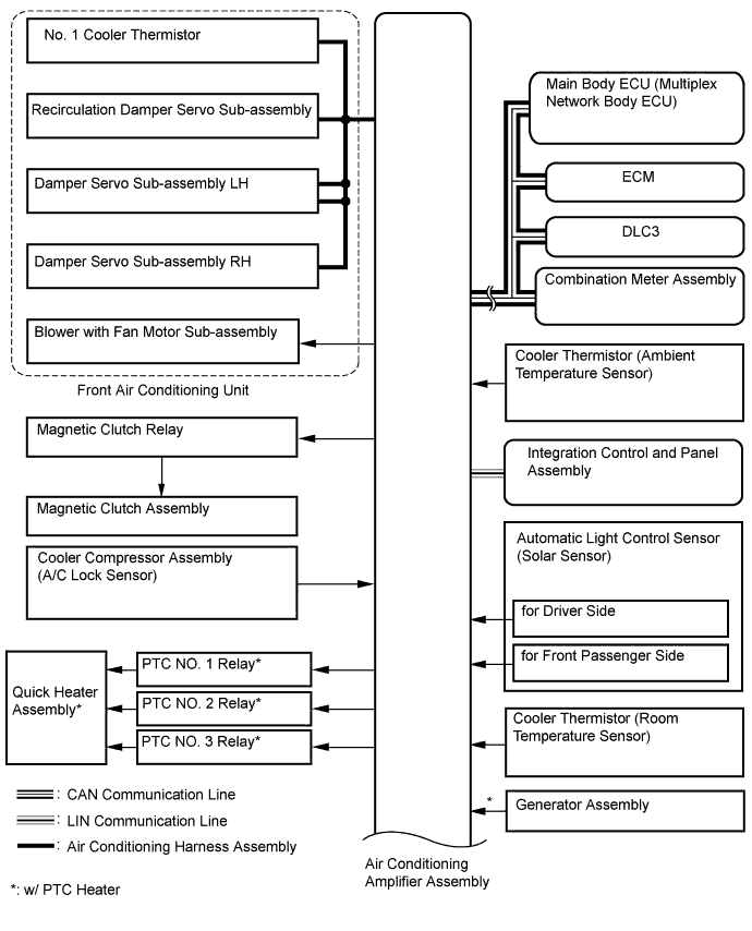

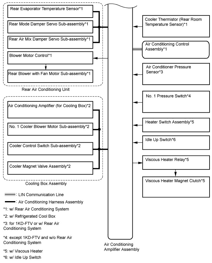
| Transmitter |
Receiver |
Signal |
Communication Line |
| Air conditioning amplifier assembly |
ECM |
A/C idle up request signal |
CAN |
| Heater idle up request signal | |||
| Viscous with magnet clutch heater control request signal*1 | |||
| PTC heater control request signal*2 | |||
| Electricity load at low voltage state signal | |||
| Refrigerant gas pressure sensor signal | |||
| Ambient temperature signal | |||
| Main body ECU |
Air conditioning amplifier assembly |
Main body request signal |
|
| Combination meter assembly |
Air conditioning amplifier assembly |
Vehicle speed signal |
|
| ECM |
Air conditioning amplifier assembly |
Engine coolant temperature signal |
|
| Engine speed data | |||
| Engine type information signal | |||
| Integration control and panel assembly |
Air conditioning amplifier assembly |
AUTO operation switch signal |
LIN |
| OFF operation switch signal | |||
| A/C switch signal | |||
| Front defroster operation switch signal | |||
| Rear defogger operation switch signal | |||
| Mode operation switch signal | |||
| REC/FRS switch signal | |||
| REAR switch signal | |||
| Set temperature switch signal | |||
| Blower operation switch signal (up, down) | |||
| Pollen removal mode switch signal | |||
| Air conditioning control assembly*3 |
Air conditioning amplifier assembly |
AUTO operation switch signal |
|
| OFF operation switch signal | |||
| Mode operation switch signal | |||
| Blower operation switch signal (up, down) | |||
| Set temperature switch signal |
- *1: w/ Viscous Heater
- *2: w/ PTC Heater
- *3: w/ Rear Air Conditioning System