Removal / installation · Vehicles built Aug 2013 – Jul 2014
Versions by build date: Aug 2013 – Jul 2014from Aug 2014
1.
INSTALL SLIDING ROOF HOUSING SUB-ASSEMBLY
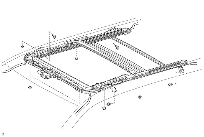
Temporarily install the sliding roof housing sub-assembly with the 4 bolts (vehicle body side) and 8 nuts.
Tighten the 8 nuts.
Torque:
5.5 N*m{
56 kgf*cm
, 49 in.*lbf
}
Tighten the 4 bolts.
Torque:
8.0 N*m{
82 kgf*cm
, 71 in.*lbf
}
Connect the 4 drain hoses.
2.
INSTALL SLIDING ROOF WEATHERSTRIP
Install the sliding roof weatherstrip as follows:
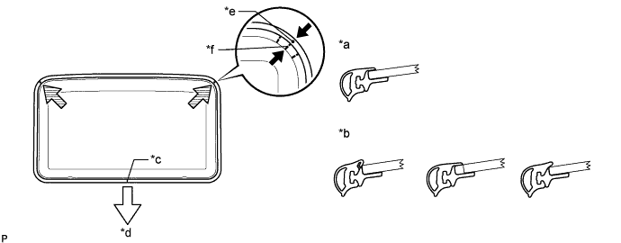
Position the joint of the sliding roof weatherstrip at the rear center.
Align the alignment mark on the sliding roof weatherstrip with the middle marks at the corners of the sliding roof glass sub-assembly and install the sliding roof weatherstrip.
Install the lip of the sliding roof weatherstrip firmly.
Text in Illustration
*a
Correct
*b
Incorrect
*c
Joint
*d
Vehicle Rear
*e
Alignment Mark
*f
Middle Mark
3.
INSTALL SLIDING ROOF GLASS SUB-ASSEMBLY
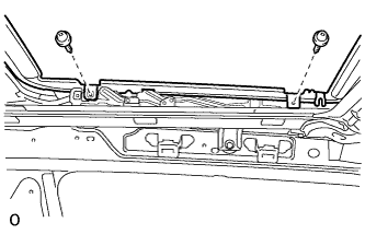
Using a T25 "TORX" driver, temporarily install the sliding roof glass sub-assembly with the 4 screws.
Perform a level check.
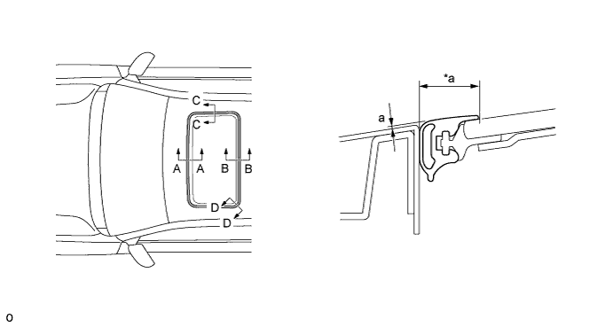
Check the difference in the level between the roof panel and upper surface of the weatherstrip labeled "a" when the sliding roof glass is fully closed.
Text in Illustration
*a
Even
-
-
Standard:
Area
Specified Condition
A - A
-2.0 to 1.0 mm (-0.0787 to 0.0394 in.)
B - B
-1.0 to 2.0 mm (-0.0394 to 0.0787 in.)
C - C
-1.5 to 1.5 mm (-0.0591 to 0.0591 in.)
D - D
-1.0 to 1.5 mm (-0.0394 to 0.0591 in.)
HINT:
"+" represents the condition that the glass is above the panel level. "-" represents the condition that the glass is below the panel level.
Perform a gap check. Check the gap between the roof panel and roof glass.
NOTICE:
The gap must be even all around.
Using a T25 "TORX" driver, tighten the 4 screws.
Torque:
5.5 N*m{
56 kgf*cm
, 49 in.*lbf
}
4.
CHECK FOR WATER LEAK
After adjusting the sliding roof glass sub-assembly, check for water leakage into the vehicle interior. If there are any leaks, readjust the sliding roof glass sub-assembly.
5.
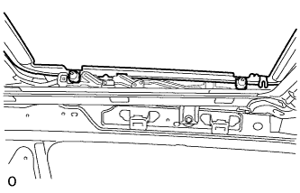
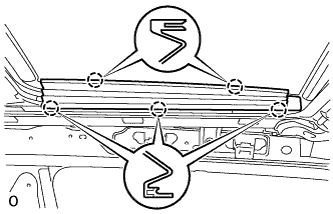
INSTALL SLIDING ROOF SIDE GARNISH LH
Attach the 5 claws to install the sliding roof side garnish LH.
6.
INSTALL SLIDING ROOF SIDE GARNISH RH
HINT:
Use the same procedure described for the LH side.
7.
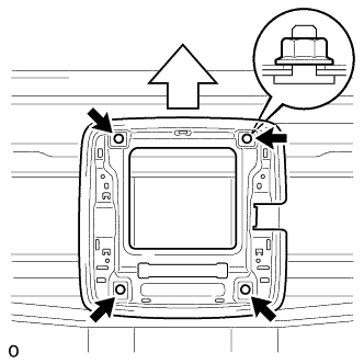
INSTALL TELEVISION DISPLAY BRACKET A (w/ Rear Seat Entertainment System)
Install the television display bracket A with the 4 nuts.
Torque:
9.0 N*m{
92 kgf*cm
, 80 in.*lbf
}
Text in Illustration
Front Side
8.
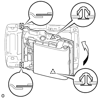
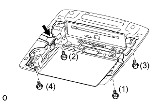
INSTALL TELEVISION DISPLAY ASSEMBLY (w/ Rear Seat Entertainment System)
Attach the television display assembly to the 2 guides on the front side of the bracket by moving it in the direction of the arrow in the illustration, and then attach 2 new clips to temporarily install the television display assembly.
Install the television display assembly with the 4 bolts in the order shown in the illustration.
Torque:
8.5 N*m{
87 kgf*cm
, 75 in.*lbf
}
Connect the connector.
9.
INSTALL REAR NO. 3 ROOF AIR DUCT (for Dual Air Conditioning System)
Install the duct with the clip.
10.
INSTALL REAR NO. 5 ROOF AIR DUCT (for Dual Air Conditioning System)