REMOVAL
Removal / installation · Vehicles built from Aug 2013
| 1. REMOVE NO. 2 INSTRUMENT PANEL FINISH PANEL CUSHION |

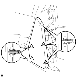  |
Detach the 5 clips and remove the No. 2 instrument panel finish panel cushion.
| 2. REMOVE INSTRUMENT PANEL FINISH PANEL END LH |
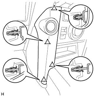 |
Detach the 4 clips and remove the instrument panel finish panel end LH.
| 3. REMOVE NO. 1 INSTRUMENT PANEL FINISH CUSHION |
- HINT:
- Use the same procedure described for the No. 2 instrument panel finish panel cushion.
| 4. REMOVE INSTRUMENT PANEL FINISH PANEL END RH |
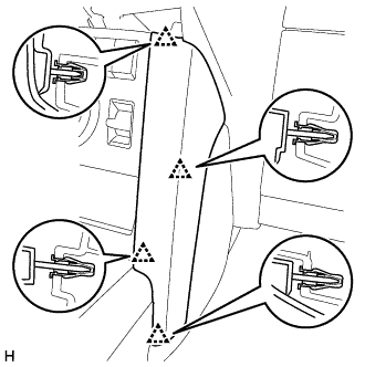 |
Detach the 4 clips and remove the instrument panel finish panel end RH.
| 5. REMOVE INTEGRATION CONTROL AND PANEL ASSEMBLY |
Detach the 4 clips.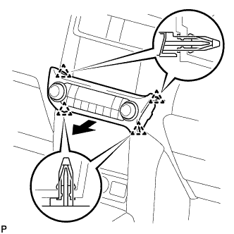
Disconnect the connector and remove the integration control and panel assembly.
| 6. REMOVE FRONT CONSOLE UPPER PANEL GARNISH |
w/o Seat Heater System:
Put protective tape around the front console upper panel garnish.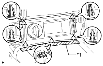
Text in Illustration *1
Protective Tape
Detach the 5 clips and remove the front console upper panel garnish.
Disconnect the connector.
w/o CRAWL:
Put protective tape around the front console upper panel garnish.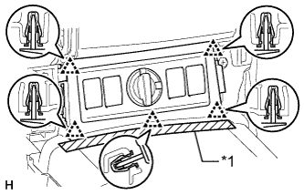
Text in Illustration *1
Protective Tape
Detach the 5 clips and remove the front console upper panel garnish.
Disconnect each connector.
w/ CRAWL:
Put protective tape around the front console upper panel garnish.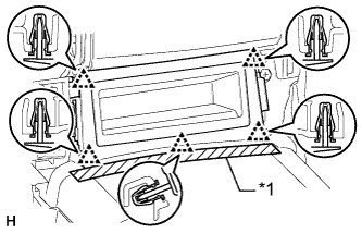
Text in Illustration *1
Protective Tape
Detach the 5 clips and remove the front console upper panel garnish.
| 7. REMOVE COMBINATION SWITCH (w/ CRAWL) |
| 8. REMOVE LOWER CENTER INSTRUMENT CLUSTER FINISH PANEL SUB-ASSEMBLY (w/o CRAWL) |
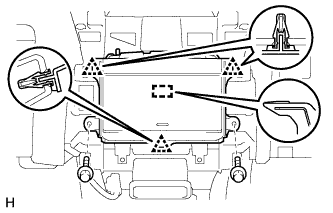 |
Remove the 2 bolts <E>.
Detach the 3 clips and guide and remove the lower center instrument cluster finish panel.
| 9. REMOVE ENGINE SWITCH |
Disconnect the connector from the engine switch.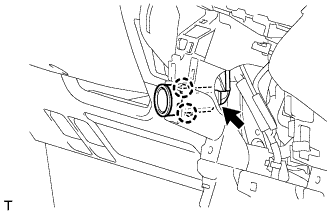
Detach the 2 claws and remove the engine switch.