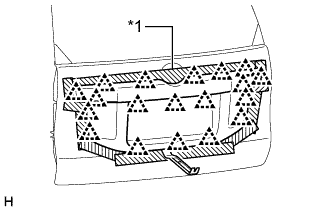
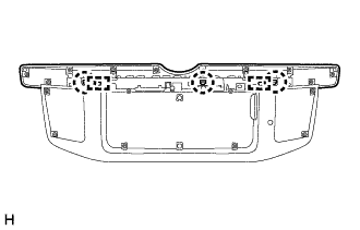
REMOVAL
Removal / installation · Vehicles built from Aug 2014
Versions by build date: Aug 2013 – Jul 2014 from Aug 2014
| 1.
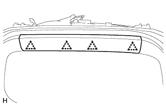
REMOVE BACK DOOR CENTER GARNISH
|
 |
- Detach the 4 clips and remove the back door center garnish.
| 2.
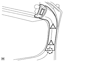
REMOVE BACK DOOR SIDE GARNISH LH
|
|
- Detach the 2 clips and claw and remove the back door side garnish.
| 3.
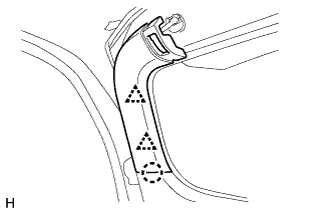
REMOVE BACK DOOR SIDE GARNISH RH
|
|
- Detach the 2 clips and claw and remove the back door side garnish.
| 4.
REMOVE BACK DOOR TRIM COVER
|
|
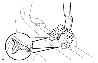
- Remove the back door trim cover as shown in the illustration.
| 5.
REMOVE UPPER TOOL BOX PANEL SUB-ASSEMBLY
|
|
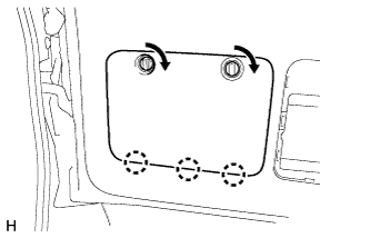
- Remove the upper tool box panel sub-assembly as shown in the illustration.
| 6.
REMOVE TOOL CASE
|
|
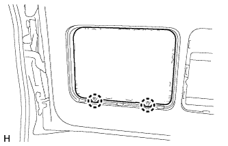
- Detach the 2 claws and remove the tool case.
| 7.
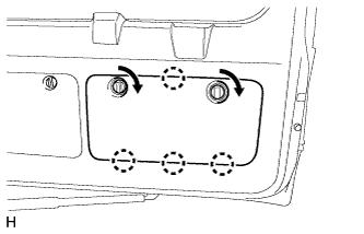
REMOVE BACK DOOR LOCK COVER
|
|
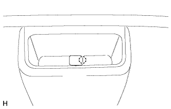
- Using moulding remover B, detach the clip and 6 claws and remove the back door lock cover.
| 8.
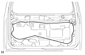
REMOVE BACK DOOR TRIM PANEL ASSEMBLY
|
|
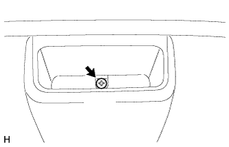
- Detach the claw and remove the cover.
- HINT:
- Tape the screwdriver tip before use.
- Remove the screw.
w/o Back Door Tire Carrier:
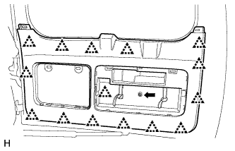
- Remove the bolt.
Detach the 15 clips and remove the back door trim panel assembly.
w/ Back Door Tire Carrier:
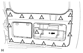
- Remove the bolt.
Detach the 16 clips and remove the back door trim panel assembly.
for Face to Face Seat Type:
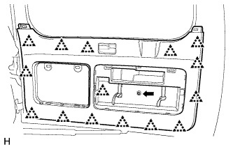
- Remove the screw and bolt.
Detach the 15 clips and remove the back door trim panel assembly.
| 9.
REMOVE BACK DOOR SERVICE HOLE COVER
|
|
- Remove the service hole cover.
| 10.
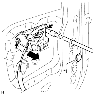
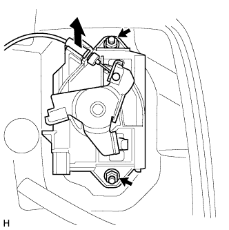
REMOVE BACK DOOR OUTSIDE HANDLE LH
|
|
w/ Back Door Tire Carrier:
- Remove the hole plug.
Text in Illustration
*1
|
Hole Plug
|
Remove the 2 nuts and back door outside handle.
Disconnect the cable.
w/o Back Door Tire Carrier:
- Remove the 2 nuts and back door outside handle.
Disconnect the cable.
| 11.
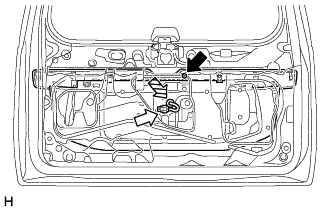
REMOVE BACK DOOR OUTSIDE GARNISH SUB-ASSEMBLY |
|
Remove the nut.
Disconnect the connector.
Detach the clamp and disconnect the back door electrical key switch wire harness from the back door panel.
- Put protective tape around the back door outside garnish sub-assembly.
Text in Illustration
*1
|
Protective Tape
|
Using moulding remover B, detach the 19 clips and remove the back door garnish sub-assembly.
| 12.
REMOVE NO. 2 BACK DOOR OUTSIDE GARNISH |
|
- Detach the 3 claws and 2 guides and remove the No. 2 back door outside garnish.