Removal / installation · Vehicles built Aug 2013 – Jul 2014
Versions by build date: Aug 2013 – Jul 2014from Aug 2014
HINT:
Use the same procedure for the RH and LH sides.
The procedure listed below is for the LH side.
1.
INSTALL FRONT DOOR INSIDE LOCKING CABLE ASSEMBLY LH
Install the front door inside locking cable assembly.
Attach the 3 claws.
2.
INSTALL FRONT DOOR LOCK REMOTE CONTROL CABLE ASSEMBLY LH
Install the front door lock remote control cable assembly.
3.
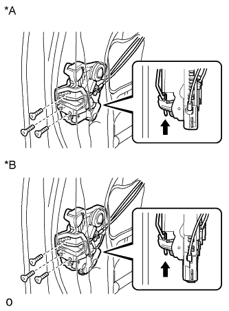
INSTALL FRONT DOOR LOCK ASSEMBLY LH
NOTICE:
When reusing the removed front door lock assembly, replace the door lock wiring harness seal on the connector with a new one.
Do not allow grease or dust to adhere to the surface of the connector which contacts the door lock wiring harness seal.
Reusing the door lock wiring harness seal or using a damaged door lock wiring harness seal may allow water into the connection. This may result in a malfunction of the front door lock assembly.
Apply MP grease to the sliding parts of the front door lock assembly.
Install a new door lock wiring harness seal to the front door lock assembly.
Insert the front door lock open rod to the front door lock assembly.
Text in Illustration
*A
w/o Double Locking System
*B
w/ Double Locking System
Slide
Check that the front door lock open rod is securely connected to the front door lock assembly.
Using a T30 "TORX" wrench, install the front door lock assembly with the 3 screws.
Torque:
5.0 N*m{
51 kgf*cm
, 44 in.*lbf
}
Connect the connector.
4.
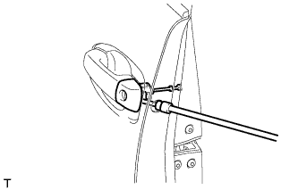
INSTALL FRONT DOOR OUTSIDE HANDLE COVER WITH LOCK CYLINDER ASSEMBLY
Install the front door outside handle cover with lock cylinder assembly.
HINT:
Make sure that the front door lock cylinder rod is inserted into the front door lock assembly.
Using a T30 "TORX" socket wrench, install the front door lock cylinder with the screw.
Torque:
4.0 N*m{
41 kgf*cm
, 35 in.*lbf
}
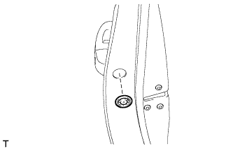
Install the hole plug.
5.
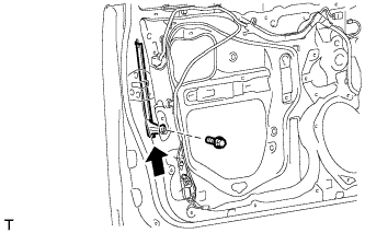
INSTALL FRONT DOOR REAR LOWER FRAME SUB-ASSEMBLY LH
Install the front door rear lower frame sub-assembly with the bolt as shown in the illustration.
6.
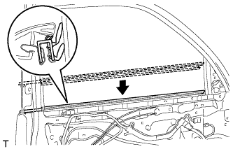
INSTALL FRONT DOOR GLASS RUN LH
Install the front door glass run.
7.
INSTALL FRONT DOOR GLASS SUB-ASSEMBLY LH
Connect the cable to the negative (-) battery terminal.
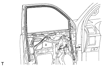
Connect the power window regulator master switch assembly and move the front door glass sub-assembly so that the door glass bolt installation locations can be seen.
Disconnect the cable from the negative (-) battery terminal and power window regulator master switch assembly.
CAUTION:
Wait at least 90 seconds after disconnecting the cable from the negative (-) battery terminal to disable the SRS system (Click here).
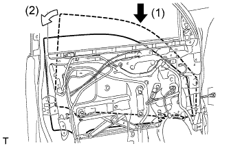
Insert the front door glass sub-assembly into the front door panel along the front door glass run as indicated by the arrows in the order shown in the illustration.
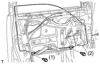
Install the front door glass sub-assembly with the 2 bolts.
Torque:
5.5 N*m{
56 kgf*cm
, 49 in.*lbf
}
HINT:
Tighten the bolts in the order shown in the illustration.
8.
INSTALL FRONT DOOR SERVICE HOLE COVER LH
Apply new butyl tape to the front door panel.
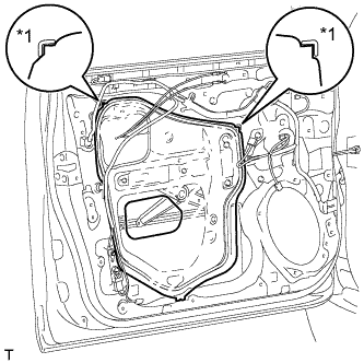
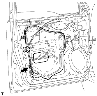
Pass the front door lock remote control cable assembly and front door inside locking cable assembly through a new front door service hole cover.
Text in Illustration
*1
Reference Point
Attach the front door service hole cover using the reference points on the front door panel.
NOTICE:
There should be no wrinkles or folds after attaching the service hole cover.
After attaching the service hole cover, check the seal quality.
NOTICE:
Securely install the front door service hole cover preventing wrinkles and air bubbles.
Attach the 2 clamps.
Install the bolt to the front door wire.
9.
INSTALL FRONT DOOR INNER GLASS WEATHERSTRIP LH
Install the front door inner glass weatherstrip.
10.
INSTALL FRONT DOOR TRIM BOARD SUB-ASSEMBLY LH
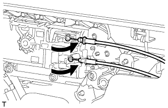
Connect the front door lock remote control cable assembly and front door inside locking cable assembly.
Connect 2 connectors.
w/ Seat Position Memory System:
Connect the connectors.
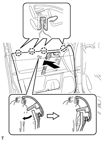
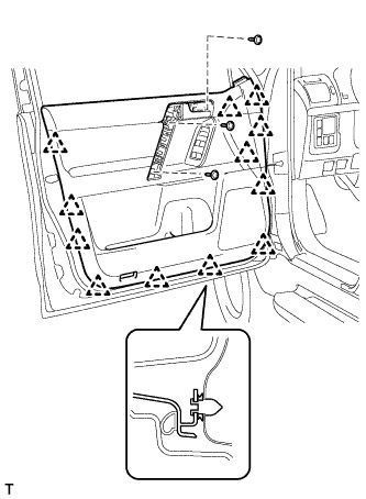
Attach the front door trim board sub-assembly by attaching the 4 claws of the front door inner glass weatherstrip as shown in the illustration.
Attach the 12 clips and front door trim board retainer to install the front door trim board sub-assembly.
Install the 3 screws.
11.
INSTALL ASSIST GRIP COVER LH
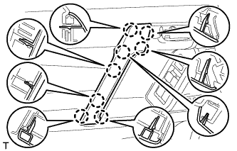
Attach the 8 claws to install the assist grip cover.
12.
INSTALL NO. 2 DOOR INSIDE HANDLE BEZEL LH
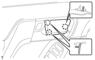
Attach the 3 claws to install the inside handle bezel.
13.
INSTALL FRONT DOOR LOWER FRAME BRACKET GARNISH LH
Attach the 2 claws to install the front door lower frame bracket garnish.
14.
CONNECT CABLE TO NEGATIVE BATTERY TERMINAL
NOTICE:
When disconnecting the cable, some systems need to be initialized after the cable is reconnected (Click here).