INSTALLATION
Removal / installation · Vehicles built from Aug 2014
Versions by build date: Aug 2013 – Jul 2014 from Aug 2014
- HINT:
- A bolt without a torque specification is shown in the standard bolt chart (Click here).
- Use the same procedure for RHD and LHD vehicles.
- The procedure listed below is for LHD vehicles.
- A bolt without a torque specification is shown in the standard bolt chart (Click here).
| 1. INSTALL DOUBLE LOCK DOOR CONTROL RELAY ASSEMBLY |

Install the double door lock control relay assembly with the nut.
Connect the connector.
| 2. INSTALL GLOVE COMPARTMENT DOOR ASSEMBLY |
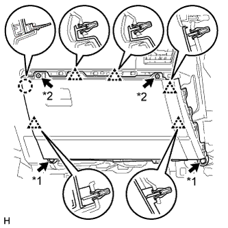  |
Connect each connector.
Attach the 5 clips and claw to install the glove compartment door.
Install the 2 bolts <C> and 2 screws <A> or <B>.
Text in Illustration *1
Bolt
*2
Screw
| 3. INSTALL NO. 2 INSTRUMENT PANEL UNDER COVER SUB-ASSEMBLY |
Attach the 3 clips and 2 guides to install the No. 2 instrument panel under cover.
Install the screw.
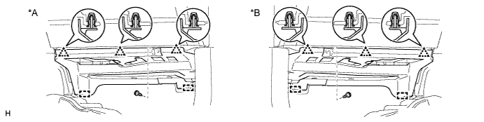
Text in Illustration *A
for LHD
*B
for RHD
| 4. INSTALL INSTRUMENT PANEL ORNAMENT |
Attach the 5 clips to install the instrument panel ornament.
| 5. INSTALL INSTRUMENT SIDE PANEL RH |
Connect the connector.
Attach the 5 clips, claw and 3 guides to install the instrument side panel.
| 6. INSTALL COWL SIDE TRIM BOARD RH |
- HINT:
- Use the same procedure described for the LH side.
| 7. INSTALL DOOR SCUFF PLATE ASSEMBLY RH |
- HINT:
- Use the same procedure described for the LH side.