Home › Engine / Hybrid System › 5L-E (ENGINE CONTROL) › ECD SYSTEM
RM27T0E _51 Engine / Hybrid System _053658 5L-E ENGINE CONTROL _0260445 ECD SYSTEM C

5L-E ENGINE CONTROL  ECD SYSTEM  P1222  Throttle Motor Circuit Range/Performance  


DESCRIPTION

Throttle control motor is operated by the ECM and opens and closes the throttle valve.

The fully open position of the throttle valve is detected by the throttle open switch which is mounted on the venturi assembly.

If this DTC is stored, the ECM shuts down the power for the throttle control motor.

DTC No. DTC Detection Condition Trouble Area
P1222 Open or short in throttle control motor circuit.
·

Open or short in throttle control motor circuit

·

Throttle control motor (Venturi assembly)

·

Intake restrictor valve

·

Open or short in throttle open switch circuit

·

Throttle open switch (Venturi assembly)

·

ECM


Open or short in throttle open switch circuit.

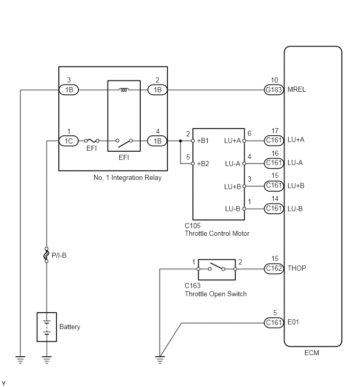
WIRING DIAGRAM

A227798E07
3.76,4.656 5.219,4.854 1.458,0.198 10 false Throttle Control Motor 3.76,5.885 5.219,6.083 1.458,0.198 10 false Throttle Open Switch 6.198,7.083 6.656,7.271 0.458,0.188 10 false ECM 5.854,1.729 6.313,1.917 0.458,0.188 10 false MREL 5.854,2.75 6.313,2.938 0.458,0.188 10 false LU+A 5.854,3.219 6.313,3.406 0.458,0.188 10 false LU-A 5.854,3.688 6.313,3.875 0.458,0.188 10 false LU+B 5.854,4.156 6.313,4.344 0.458,0.188 10 false LU-B 5.854,5.365 6.313,5.552 0.458,0.188 10 false THOP 5.854,6.458 6.313,6.646 0.458,0.188 10 false E01 1.052,5.104 1.688,5.292 0.635,0.188 10 false P/I-B 1.208,6.552 1.781,6.74 0.573,0.188 10 false Battery 1.906,3.521 3.396,3.729 1.49,0.208 10 false No. 1 Integration Relay 2.417,3.115 2.76,3.333 0.344,0.219 10 false EFI 1.76,2.927 2.167,3.167 0.406,0.24 10 false EFI 5.417,6.469 5.906,6.646 0.49,0.177 10 false C161 5.406,1.74 5.896,1.906 0.49,0.167 10 false G183 5.563,6.271 5.813,6.448 0.25,0.177 10 false 5 5.51,1.542 5.76,1.708 0.25,0.167 10 false 10 3.792,2.635 4.042,2.802 0.25,0.167 10 false 2 3.792,3.104 4.042,3.271 0.25,0.167 10 false 5 3.125,1.74 3.333,1.906 0.208,0.167 10 false 1B 3.167,1.542 3.344,1.708 0.177,0.167 10 false 2 3.125,2.781 3.333,2.948 0.208,0.167 10 false 1B 3.177,2.583 3.354,2.75 0.177,0.167 10 false 4 1.313,2.781 1.521,2.948 0.208,0.167 10 false 1C 1.365,2.583 1.542,2.75 0.177,0.167 10 false 1 1.323,1.74 1.531,1.906 0.208,0.167 10 false 1B 1.365,1.542 1.542,1.708 0.177,0.167 10 false 3 4.563,2.771 5.021,2.958 0.458,0.188 10 false LU+A 4.583,3.24 5.042,3.427 0.458,0.188 10 false LU-A 4.563,3.708 5.021,3.896 0.458,0.188 10 false LU+B 4.583,4.156 5.042,4.344 0.458,0.188 10 false LU-B 4.01,2.771 4.469,2.958 0.458,0.188 10 false +B1 4.01,3.24 4.469,3.427 0.458,0.188 10 false +B2 3.76,4.5 4.219,4.688 0.458,0.188 10 false C105 5.042,2.625 5.229,2.813 0.188,0.188 10 false 6 5.042,3.094 5.229,3.281 0.188,0.188 10 false 4 5.042,3.552 5.229,3.74 0.188,0.188 10 false 3 5.042,4.01 5.229,4.198 0.188,0.188 10 false 1 5.417,5.365 5.906,5.542 0.49,0.177 10 false C162 5.521,5.167 5.771,5.344 0.25,0.177 10 false 15 5.417,4.146 5.906,4.323 0.49,0.177 10 false C161 5.521,3.948 5.771,4.125 0.25,0.177 10 false 14 5.417,3.677 5.906,3.854 0.49,0.177 10 false C161 5.521,3.479 5.771,3.656 0.25,0.177 10 false 15 5.417,3.219 5.906,3.396 0.49,0.177 10 false C161 5.521,3.031 5.771,3.208 0.25,0.177 10 false 16 5.417,2.76 5.906,2.938 0.49,0.177 10 false C161 5.521,2.573 5.771,2.75 0.25,0.177 10 false 17 3.76,5.719 4.219,5.906 0.458,0.188 10 false C163 3.906,5.24 4.094,5.427 0.188,0.188 10 false 1 4.854,5.24 5.104,5.406 0.25,0.167 10 false 2

CAUTION / NOTICE / HINT

NOTICE:

Inspect the fuses for circuits related to this system before performing the following inspection procedure.


HINT:

Read freeze frame data using the GTS. Freeze frame data records the engine condition when malfunctions are detected. When troubleshooting, freeze frame data can help determine if the vehicle was moving or stationary, if the engine was warmed up or not, and other data from the time the malfunction occurred.


PROCEDURE
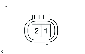
1.INSPECT THROTTLE OPEN SWITCH
a.
A106810E01
0.179,0.201 0.370,0.375 0.191,0.173 10 *a

Disconnect the throttle open switch connector.


b.

Remove the venturi assembly.


c.

Measure the resistance according to the value(s) in the table below.

Standard Resistance:
Tester Connection Condition Specified Condition
1 - 2 Throttle valve is opened Below 1 Ω
1 - 2 Throttle valve is closed 10 kΩ or higher


Text in Illustration
*a Component without harness connected
(Throttle Open Switch)

HINT:

The throttle open switch is integrated with the venturi assembly. If the throttle open switch is replaced, the venturi assembly must be replaced in whole.


OK

2.CHECK HARNESS AND CONNECTOR (THROTTLE OPEN SWITCH - BODY GROUND, ECM - THROTTLE OPEN SWITCH)

NG

REPLACE VENTURI ASSEMBLY

2.CHECK HARNESS AND CONNECTOR (THROTTLE OPEN SWITCH - BODY GROUND, ECM - THROTTLE OPEN SWITCH)
a.

Disconnect the throttle open switch connector.


b.

Disconnect the ECM connector.


c.

Measure the resistance according to the value(s) in the table below.

Standard Resistance:
Tester Connection Condition Specified Condition
C163-2 - C162-15 (THOP) Always Below 1 Ω
C163-1 - Body ground Always Below 1 Ω
C163-2 or C162-15 (THOP) - Body ground Always 10 kΩ or higher


OK

3.CHECK TERMINAL VOLTAGE (THROTTLE CONTROL MOTOR)

NG

REPAIR OR REPLACE HARNESS OR CONNECTOR

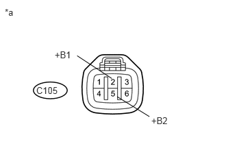
3.CHECK TERMINAL VOLTAGE (THROTTLE CONTROL MOTOR)
a.
U169189E01
0.551,1.289 0.934,1.441 0.383,0.152 10 C105 0.832,0.752 1.308,0.899 0.476,0.147 10 +B1 1.7,1.192 1.173,0.846 false 0.074,0.106 0.273,0.258 0.199,0.152 10 *a 2.301,1.752 2.633,1.899 0.332,0.147 10 +B2 2.272,1.771 1.782,1.468 false

Disconnect the throttle control motor connector.


b.

Measure the voltage according to the value(s) in the table below.

Standard Voltage:
Tester Connection Switch Condition Specified Condition
C105-2 (+B1) - Body ground Ignition switch ON 11 to 14 V
C105-5 (+B2) - Body ground Ignition switch ON 11 to 14 V


Text in Illustration
*a Front view of wire harness connector
(to Throttle Control Motor)


OK

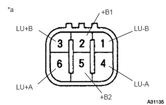
4.INSPECT THROTTLE CONTROL MOTOR

NG

REPAIR OR REPLACE HARNESS OR CONNECTOR (THROTTLE CONTROL MOTOR - NO. 1 INTEGRATION RELAY)

4.INSPECT THROTTLE CONTROL MOTOR
a.
A031135E05
0.333,0.51 0.748,0.676 0.415,0.165 10 LU+B 0.802,0.633 1.155,0.862 false 0.333,1.73 0.748,1.877 0.415,0.147 10 LU+A 0.785,1.75 1.155,1.429 false 2.069,1.937 2.401,2.084 0.332,0.147 10 +B2 2.108,1.939 1.757,1.515 false 2.774,0.51 3.170,0.680 0.397,0.170 10 LU-B 2.744,0.65 2.255,0.862 false 2.095,0.164 2.571,0.311 0.476,0.147 10 +B1 1.794,0.741 2.058,0.275 false 2.774,1.662 3.170,1.832 0.397,0.170 10 LU-A 2.744,1.681 2.255,1.378 false 0.155,0.11 0.425,0.318 0.270,0.208 10 *a

Disconnect the throttle control motor connector.


b.

Measure the resistance according to the value(s) in the table below.

Standard Resistance:
Tester Connection Condition Specified Condition
1 (LU-B) - 2 (+B1) 20°C (68°F) 18 to 22 Ω
2 (+B1) - 3 (LU+B) 20°C (68°F) 18 to 22 Ω
4 (LU-A) - 5 (+B2) 20°C (68°F) 18 to 22 Ω
5 (+B2) - 6 (LU+A) 20°C (68°F) 18 to 22 Ω


Text in Illustration
*a Component without harness connected
(Throttle Control Motor)

HINT:

The throttle control motor is integrated with the venturi assembly. If the throttle control motor is replaced, the venturi assembly must be replaced in whole.


OK

5.CHECK HARNESS AND CONNECTOR (THROTTLE CONTROL MOTOR - ECM)

NG

REPLACE VENTURI ASSEMBLY

5.CHECK HARNESS AND CONNECTOR (THROTTLE CONTROL MOTOR - ECM)
a.

Disconnect the throttle control motor connector.


b.

Disconnect the ECM connector.


c.

Measure the resistance according to the value(s) in the table below.

Standard Resistance:
Tester Connection Condition Specified Condition
C105-6 (LU+A) - C161-17 (LU+A) Always Below 1 Ω
C105-4 (LU-A) - C161-16 (LU-A) Always Below 1 Ω
C105-3 (LU+B) - C161-15 (LU+B) Always Below 1 Ω
C105-1 (LU-B) - C161-14 (LU-B) Always Below 1 Ω
C105-6 (LU+A) or C161-17 (LU+A) - Body ground Always 10 kΩ or higher
C105-4 (LU-A) or C161-16 (LU-A) - Body ground Always 10 kΩ or higher
C105-3 (LU+B) or C161-15 (LU+B) - Body ground Always 10 kΩ or higher
C105-1 (LU-B) or C161-14 (LU-B) - Body ground Always 10 kΩ or higher


OK

NG
REPAIR OR REPLACE HARNESS OR CONNECTOR