1GD-FTV FUEL FUEL SENDER GAUGE ASSEMBLY(for Double Tank Type) INSTALLATION
PROCEDURE

 83320
1.INSTALL FUEL SENDER GAUGE ASSEMBLY (for Fuel Main Tank)
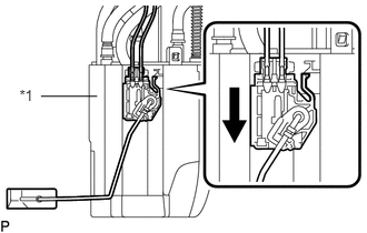
Set the fuel sender gauge assembly on the fuel sub-tank. Then slide the fuel sender gauge assembly downward to install it.
| *1 | Fuel Sub-Tank |

|
Slide |
Connect the fuel sender gauge assembly connector.
83320B
2.INSTALL FUEL SENDER GAUGE ASSEMBLY (for Fuel Sub Tank)
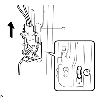
Set the fuel sender gauge assembly on the fuel gauge support. Then slide the fuel sender gauge assembly upward to install it.
| *1 | Fuel Gauge Support |
|
|
Slide |
- NOTICE:
-
Make sure the part labeled A in the illustration is securely inserted into the hole of the fuel gauge support before sliding the fuel sender gauge assembly upward.
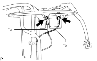
Install the 2 lead wires with the 2 screws.
- Torque:
- 2.0 N*m (20 kgf*cm, 18 in.*lbf)
| *a | Lead Wire (Black) |
| *b | Lead Wire (Red) |
- NOTICE:
-
Be sure to install the lead wires in the correct locations according to their color as shown in the illustration.
77010
3.INSTALL FUEL TANK VENT TUBE ASSEMBLY (for Fuel Sub Tank)
77020A
4.INSTALL FUEL SUCTION WITH PUMP AND GAUGE TUBE ASSEMBLY (for Fuel Main Tank)