RM27T0E
_54
Brake
_053712
BRAKE CONTROL / DYNAMIC CONTROL SYSTEMS
_0260912
VEHICLE STABILITY CONTROL SYSTEM(for Vacuum Brake Booster)
J
BRAKE CONTROL / DYNAMIC CONTROL SYSTEMS VEHICLE STABILITY CONTROL SYSTEM(for Vacuum Brake Booster) TS and CG Terminal Circuit
DESCRIPTION
The signal check circuit detects trouble in the sensor or switch signal which cannot be detected by the DTC check.
Connecting terminals TS and CG of the DLC3 starts the signal check.
WIRING DIAGRAM
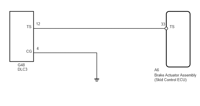
0.633,2.247 0.936,2.404
0.303,0.157
10
G48
0.938,1.761 1.194,1.923
0.255,0.162
10
CG
0.952,0.878 1.208,1.040
0.255,0.162
10
TS
1.288,0.773 1.485,0.928
0.198,0.156
10
12
1.309,1.652 1.506,1.808
0.198,0.156
10
4
6.078,0.879 6.279,1.028
0.201,0.149
10
TS
5.767,0.781 5.940,0.930
0.173,0.149
10
33
5.532,2.615 7.153,2.987
1.621,0.372
10
Brake Actuator Assembly (Skid Control ECU)
0.633,2.409 1.019,2.566
0.386,0.157
10
DLC3
5.532,2.431 6.471,2.605
0.938,0.174
10
A6
CAUTION / NOTICE / HINT
- NOTICE:
-
When replacing the brake actuator assembly, perform calibration (See page Brake>BRAKE CONTROL / DYNAMIC CONTROL SYSTEMS>VEHICLE STABILITY CONTROL SYSTEM(for Vacuum Brake Booster)>CALIBRATION).
PROCEDURE
1.CHECK HARNESS AND CONNECTOR (SKID CONTROL ECU - DLC3)
a.
Turn the ignition switch off.
b.
Disconnect the A6 skid control ECU connector.
c.
Measure the resistance according to the value(s) in the table below.
- Standard Resistance:
Tester Connection Condition Specified Condition A6-33 (TS) - G48-12 (TS) Always Below 1 Ω
OK
2.CHECK HARNESS AND CONNECTOR (DLC3 - BODY GROUND)
NG
REPAIR OR REPLACE HARNESS OR CONNECTOR
2.CHECK HARNESS AND CONNECTOR (DLC3 - BODY GROUND)
OK
3.CHECK HARNESS AND CONNECTOR (DLC3 - BODY GROUND)
NG
REPAIR OR REPLACE HARNESS OR CONNECTOR
3.CHECK HARNESS AND CONNECTOR (DLC3 - BODY GROUND)
a.
Measure the resistance according to the value(s) in the table below.
- Standard Resistance:
Tester Connection Condition Specified Condition G48-12 (TS) - Body ground Always 10 kΩ or higher
OK
REPLACE BRAKE ACTUATOR ASSEMBLY
NG
REPAIR OR REPLACE HARNESS OR CONNECTOR