BRAKE SYSTEM (OTHER) HYDRAULIC BRAKE BOOSTER(for LHD) INSTALLATION
PROCEDURE

 44785
1.INSTALL BRAKE BOOSTER GASKET
Install a new brake booster gasket to the hydraulic brake booster.
2.INSTALL HYDRAULIC BRAKE BOOSTER ASSEMBLY
Install the hydraulic brake booster assembly with the 4 nuts.
- Torque:
- 14 N*m (145 kgf*cm, 10 ft.*lbf)
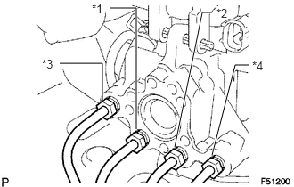
Connect the 4 brake lines to the correct positions of the hydraulic brake booster assembly as shown in the illustration.
- HINT:
- ·
*1: To front wheel cylinder RH
·*2: To front wheel cylinder LH
·*3: To rear wheel cylinder RH
·*4: To rear wheel cylinder LH
Using a union nut wrench, connect the 4 brake lines to the hydraulic brake booster assembly.
- Torque:
- 15 N*m (155 kgf*cm, 11 ft.*lbf)
- NOTICE:
-
Use the formula to calculate special torque values for situations where a union nut wrench is combined with a torque wrench (See page General>INTRODUCTION>REPAIR INSTRUCTION>PRECAUTION).
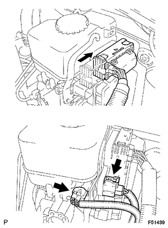
Connect the 3 connectors to the hydraulic brake booster.
47264A
3.INSTALL PUSH ROD PIN
73900
4.INSTALL LOWER NO. 1 INSTRUMENT PANEL AIRBAG ASSEMBLY
Install the lower No. 1 instrument panel airbag assembly (See page Vehicle Interior>SUPPLEMENTAL RESTRAINT SYSTEMS>KNEE AIRBAG ASSEMBLY>INSTALLATION).
5.CONNECT CABLE TO NEGATIVE BATTERY TERMINAL
- NOTICE:
-
When disconnecting the cable, some systems need to be initialized after the cable is reconnected (See page General>INTRODUCTION>REPAIR INSTRUCTION>INITIALIZATION).
6.BLEED BRAKE SYSTEM
7.CHECK AND ADJUST BRAKE PEDAL
Check and adjust brake pedal (See page Brake>BRAKE SYSTEM (OTHER)>BRAKE PEDAL (for Hydraulic Brake Booster)>ADJUSTMENT).
47217
8.INSPECT BRAKE MASTER CYLINDER OPERATION
Inspect the brake master cylinder operation (See page Brake>BRAKE SYSTEM (OTHER)>HYDRAULIC BRAKE BOOSTER(for LHD)>ON-VEHICLE INSPECTION).
89180
9.PERFORM YAW RATE AND ACCELERATION SENSOR ZERO POINT CALIBRATION
- NOTICE:
-
When replacing the hydraulic brake booster assembly, perform yaw rate and acceleration sensor zero point calibration and acquire information about the following specification as necessary (See page Brake>BRAKE CONTROL / DYNAMIC CONTROL SYSTEMS>VEHICLE STABILITY CONTROL SYSTEM (for Hydraulic Brake Booster)>CALIBRATION).
- ·
Downhill assist control calibration
·Crawl control calibration