POWER ASSIST SYSTEMS VANE PUMP(for 1KD-FTV) REASSEMBLY
CAUTION / NOTICE / HINT
- NOTICE:
-
When installing parts, coat the parts indicated by arrows with power steering fluid (See page Steering>POWER ASSIST SYSTEMS>VANE PUMP (for 1KD-FTV)>COMPONENTS).
PROCEDURE

 1.INSTALL VANE PUMP HOUSING OIL SEAL
Coat the lip of a new vane pump housing oil seal with MP grease.
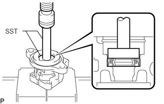
Using SST and a press, install the vane pump housing oil seal to the vane pump front housing.
- SST
- 09950-60010 (09951-00320)
09950-70010 (09951-07150)
- NOTICE:
-
Make sure that the vane pump housing oil seal is installed so that it is facing in the correct direction as shown in the illustration.
2.INSTALL VANE PUMP SHAFT BEARING
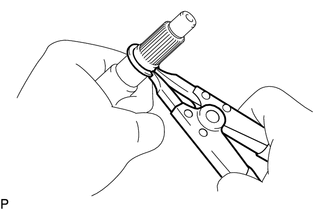
Using a snap ring expander, install the vane pump shaft snap ring to the vane pump shaft.
Wrap the serration of the vane pump shaft with protective tape.
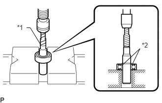
Using a press, install the vane pump shaft bearing to the vane pump shaft.
- NOTICE:
- ·
Do not damage the vane pump shaft bearing.
·Make sure that the vane pump shaft bearing inner race sits on the V-blocks.
| *1 | Protective Tape |
| *2 | Inner Race |
3.INSTALL VANE PUMP GEAR
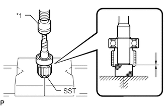
Using SST and a press, install the vane pump gear to the vane pump shaft.
- SST
- 09950-60010 (09951-00250)
| *1 | Press |
- HINT:
-
Press in the vane pump shaft until the end faces of the shaft and vane pump gear become aligned.
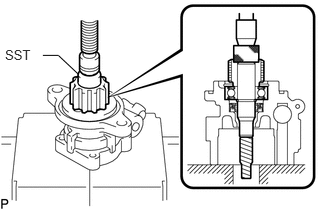
Using SST and a press, install the vane pump shaft to the vane pump front housing.
- SST
- 09950-60010 (09951-00250)
- HINT:
-
Press in the vane pump shaft until the snap ring groove of the vane pump front housing can be seen.
Install the vane pump housing snap ring No. 1 to the vane pump front housing.
4.INSTALL VANE PUMP FRONT SIDE PLATE
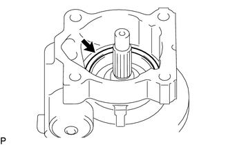
Coat a new O-ring with power steering fluid and install it to the vane pump front housing.
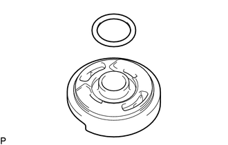
Coat a new O-ring with power steering fluid and install it to the vane pump front side plate.
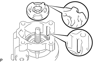
Align the notch of the vane pump front side plate with that of the vane pump front housing and install the vane pump front side plate.
- NOTICE:
-
Make sure that the vane pump front side plate is installed so that it is facing in the correct direction as shown in the illustration.
5.INSTALL VANE PUMP CAM RING
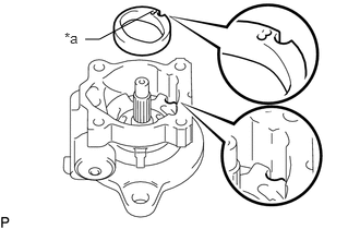
Align the notch of the vane pump cam ring with that of the vane pump front side plate and install the vane pump cam ring with the inscribed mark facing upward.
| *a | Inscribed Mark |
- NOTICE:
-
Make sure that the cam ring is installed so that it is facing in the correct direction.
6.INSTALL VANE PUMP ROTOR
Coat the vane pump rotor with power steering fluid.
Install the vane pump rotor.
- HINT:
-
The vane pump rotor has no specific direction.
Coat all 10 vane pump plates with power steering fluid.
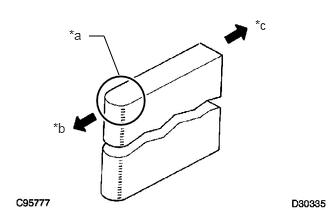
Install the vane pump plates with the round end facing outward.
| *a | Round End |
| *b | Outward |
| *c | Inward |
- NOTICE:
-
Make sure that the vane pump plates are installed so that they are facing in the correct direction.
7.INSTALL VANE PUMP REAR HOUSING
Coat a new O-ring with power steering fluid and install it to the vane pump rear housing.
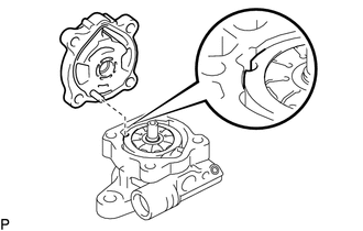
Align the straight pin of the vane pump rear housing with the notches of the vane pump cam ring, vane pump front side plate and the vane pump front housing, and install vane pump rear housing with the 4 bolts.
- Torque:
- 22 N*m (224 kgf*cm, 16 ft.*lbf)
44310
8.SECURE VANE PUMP ASSEMBLY
9.INSPECT TOTAL PRELOAD
Check that the pump rotates smoothly without abnormal noise.
Temporarily install a service bolt.
- Recommended Service Bolt:
Item Specified Condition Thread diameter 10 mm (0.394 in.) Thread pitch 1.25 mm (0.0492 in.) Bolt length 50 mm (1.97 in.)
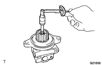
Using a torque wrench, check the rotating torque.
- Standard Rotating torque:
0.3 N*m (3 kgf*cm, 2 in.*lbf) or less
If the rotating torque is not as specified, check the installation condition of each part.
10.INSTALL SUCTION PORT UNION
Coat a new O-ring with power steering fluid and install it to the suction port union.
Install the suction port union to the vane pump front housing with the bolt.
- Torque:
- 12 N*m (122 kgf*cm, 9 ft.*lbf)