NAVIGATION / MULTI INFO DISPLAY NAVIGATION SYSTEM(for Navigation Receiver Type) B158F AV Signal Stoppage (Low Battery Voltage)
DESCRIPTION
This DTC is stored when a video or audio signal is interrupted due to battery voltage input to the navigation receiver assembly dropping temporarily.
| DTC Code | DTC Detection Condition | Trouble Area |
|---|---|---|
| B158F | A video or audio signal is interrupted when the battery voltage drops. | ·
Navigation receiver assembly ·
Harness or connector |
WIRING DIAGRAM
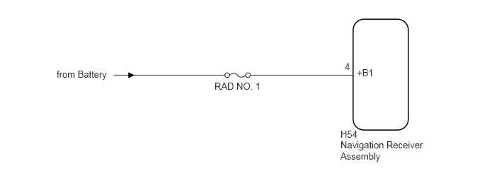
CAUTION / NOTICE / HINT
- NOTICE:
-
Inspect the fuses for circuits related to this system before performing the following procedure.
- HINT:
-
When replacing the navigation receiver assembly, it is necessary to perform the vehicle contract setting for Connected Services (w/ Connected Services Function).
PROCEDURE
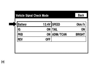
Enter the "Vehicle Signal Check Mode" screen. [Refer to Check Vehicle Signal in Operation Check (See page Audio / Visual / Telematics>NAVIGATION / MULTI INFO DISPLAY>NAVIGATION SYSTEM (for Navigation Receiver Type)>OPERATION CHECK)]
Check that the battery voltage.
- Standard voltage:
11 to 14 V
- HINT:
-
This display is updated once per second. As a result, it is normal for the display to lag behind the actual switch operation.
OK
NG
Check for DTCs (See page Audio / Visual / Telematics>NAVIGATION / MULTI INFO DISPLAY>NAVIGATION SYSTEM (for Navigation Receiver Type)>DTC CHECK / CLEAR).
- OK:
No DTCs are output.
OK
(See pageGeneral>INTRODUCTION>HOW TO TROUBLESHOOT ECU CONTROLLED SYSTEMS>HOW TO PROCEED WITH TROUBLESHOOTING)
NG
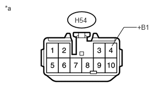
Disconnect the navigation receiver assembly connector.
Measure the voltage according to the value(s) in the table below.
- Standard Voltage:
Tester Connection Condition Specified Condition H54-4 (+B1) - Body ground Always 11 to 14 V
| *a | Front view of wire harness connector
(to Navigation Receiver Assembly) |
OK
NG