RM27T0E
_56
Audio / Visual / Telematics
_053722
PARK ASSIST / MONITORING
_0261010
REAR VIEW MONITOR SYSTEM(for Navigation Receiver Type)
J
PARK ASSIST / MONITORING REAR VIEW MONITOR SYSTEM(for Navigation Receiver Type) Image from Camera for Rear View Monitor is Abnormal
DESCRIPTION
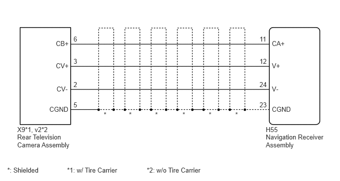
This is the display signal circuit between the navigation receiver assembly and the rear television camera assembly.
WIRING DIAGRAM
5.603,2.651 5.915,2.805
0.312,0.154
10
H55
4.959,2.332 5.271,2.486
0.312,0.154
10
*
5.47,2.123 5.782,2.278
0.312,0.154
10
23
5.47,1.695 5.782,1.849
0.312,0.154
10
24
5.47,1.208 5.782,1.362
0.312,0.154
10
12
5.47,0.737 5.782,0.891
0.312,0.154
10
11
1.549,2.123 1.861,2.278
0.312,0.154
10
5
1.549,1.695 1.861,1.849
0.312,0.154
10
2
1.549,1.208 1.861,1.362
0.312,0.154
10
3
1.549,0.737 1.861,0.891
0.312,0.154
10
6
5.73,2.219 6.173,2.374
0.443,0.154
10
CGND
5.73,1.791 6.042,1.945
0.312,0.154
10
V-
5.73,1.304 6.042,1.458
0.312,0.154
10
V+
5.73,0.833 6.042,0.987
0.312,0.154
10
CA+
1.04,2.219 1.474,2.374
0.434,0.154
10
CGND
1.191,1.791 1.503,1.945
0.312,0.154
10
CV-
1.177,1.304 1.489,1.458
0.312,0.154
10
CV+
1.177,0.833 1.489,0.987
0.312,0.154
10
CB+
4.4,2.332 4.712,2.486
0.312,0.154
10
*
3.847,2.332 4.159,2.486
0.312,0.154
10
*
3.27,2.332 3.582,2.486
0.312,0.154
10
*
2.719,2.332 3.031,2.486
0.312,0.154
10
*
2.187,2.332 2.499,2.486
0.312,0.154
10
*
5.603,2.802 6.887,3.151
1.285,0.349
10
Navigation Receiver Assembly
0.363,2.651 1.527,2.805
1.164,0.154
10
X9*1, v2*2
0.363,2.802 1.658,3.129
1.295,0.327
10
Rear Television Camera Assembly
0.153,3.498 1.001,3.640
0.848,0.142
10
*: Shielded
1.414,3.498 2.699,3.640
1.285,0.142
10
*1: w/ Tire Carrier
3.095,3.498 4.380,3.640
1.285,0.142
10
*2: w/o Tire Carrier
PROCEDURE
1.CHECK HARNESS AND CONNECTOR (NAVIGATION RECEIVER ASSEMBLY - REAR TELEVISION CAMERA ASSEMBLY)
OK
2.CHECK NAVIGATION RECEIVER ASSEMBLY
NG
REPAIR OR REPLACE HARNESS OR CONNECTOR
2.CHECK NAVIGATION RECEIVER ASSEMBLY
OK
3.CHECK REAR TELEVISION CAMERA ASSEMBLY
NG
REPLACE NAVIGATION RECEIVER ASSEMBLY
3.CHECK REAR TELEVISION CAMERA ASSEMBLY
a.
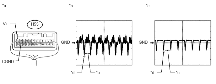
Using an oscilloscope, check the waveform.
0.093,0.705 0.331,0.874
0.238,0.169
10
V+
0.072,0.105 0.310,0.274
0.238,0.169
10
*a
2.286,0.105 2.524,0.274
0.238,0.169
10
*b
2.342,2.333 2.580,2.502
0.238,0.169
10
*d
4.836,0.105 5.074,0.274
0.238,0.169
10
*c
2.022,1.326 2.427,1.495
0.404,0.169
10
GND
1.028,0.724 1.432,0.893
0.404,0.169
10
H55
4.6,1.326 5.005,1.495
0.404,0.169
10
GND
0.062,1.966 0.526,2.135
0.464,0.169
10
CGND
0.581,1.311 0.497,0.767
0.497,0.767 0.337,0.767
false
0.581,1.311 0.497,0.767
0.497,0.767 0.337,0.767
false
0.693,1.48 0.61,2.028
0.61,2.028 0.519,2.028
false
0.693,1.48 0.61,2.028
0.61,2.028 0.519,2.028
false
2.795,1.858 2.711,2.406
2.711,2.406 2.551,2.406
false
2.795,1.858 2.711,2.406
2.711,2.406 2.551,2.406
false
3.182,2.333 3.421,2.502
0.238,0.169
10
*e
2.915,1.76 2.999,2.406
2.999,2.406 3.159,2.406
false
2.915,1.76 2.999,2.406
2.999,2.406 3.159,2.406
false
4.99,2.333 5.228,2.502
0.238,0.169
10
*d
5.429,1.718 5.359,2.406
5.359,2.406 5.199,2.406
false
5.429,1.718 5.359,2.406
5.359,2.406 5.199,2.406
false
5.83,2.333 6.069,2.502
0.238,0.169
10
*e
5.563,1.662 5.647,2.406
5.647,2.406 5.807,2.406
false
5.563,1.662 5.647,2.406
5.647,2.406 5.807,2.406
false
| *a | Component with harness connected
(Navigation Receiver Assembly) |
*b | Waveform 1 |
| *c | Waveform 2 | *d | Synchronized Signal |
| *e | Video Waveform | - | - |
| Item | Content |
|---|---|
| Tester Connection | H55-12 (V+) - H55-23 (CGND) |
| Tool Setting | 200 mV/DIV., 50 μs/DIV. |
| Condition | Waveform 1: Ignition switch ON, camera lens not covered, displaying an image Waveform 2: Ignition switch ON, camera lens covered, blacking out screen |
- OK:
Waveform is as shown in illustration.
- HINT:
-
The video waveform changes according to the image sent by the television camera assembly.
| Result | Proceed to |
|---|---|
| OK | A |
| NG (w/ Tire Carrier) | B |
| NG (w/o Tire Carrier) | C |
A
PROCEED TO NEXT SUSPECTED AREA SHOWN IN PROBLEM SYMPTOMS TABLE
B
REPLACE REAR TELEVISION CAMERA ASSEMBLY
C
REPLACE REAR TELEVISION CAMERA ASSEMBLY