RM27T0E
_57
Power Source / Network
_053729
NETWORKING
_0261031
CAN COMMUNICATION SYSTEM(for LHD with Entry and Start System)
C
NETWORKING CAN COMMUNICATION SYSTEM(for LHD with Entry and Start System) U010E/A2 Lost Communication with Reductant Control Module
DESCRIPTION
| DTC Code | DTC Detection Condition | Trouble Area |
|---|---|---|
| U010E/A2 | There is no communication from the urea pump control ECU. | ·
Power source or inside of urea pump control ECU ·
Urea pump control ECU |
For vehicle with a urea SCR system.
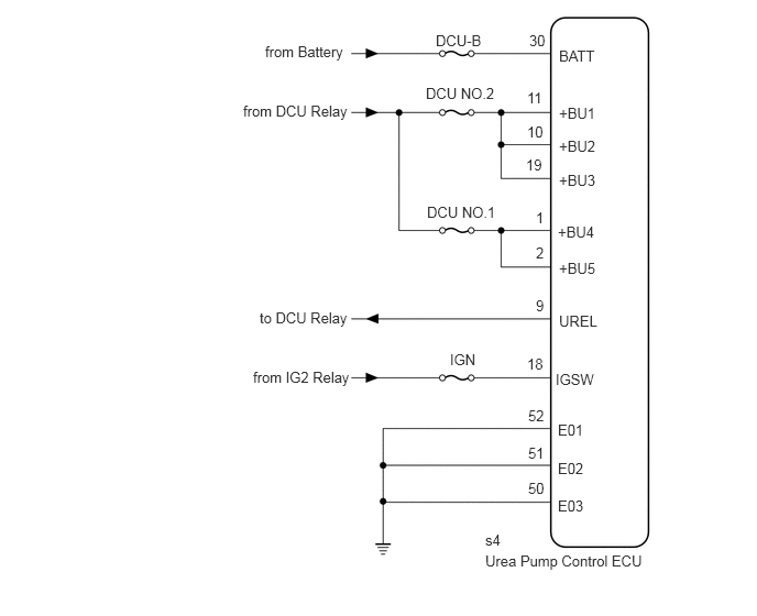
WIRING DIAGRAM
4.594,5.229 6.781,5.427
2.188,0.198
10
false
Urea Pump Control ECU
5.292,0.448 5.906,0.646
0.615,0.198
10
false
BATT
5.26,3.51 5.875,3.708
0.615,0.198
10
false
IGSW
5.281,3.99 5.896,4.188
0.615,0.198
10
false
E01
5.281,4.354 5.896,4.552
0.615,0.198
10
false
E02
5.281,4.708 5.896,4.906
0.615,0.198
10
false
E03
4.125,0.302 4.896,0.5
0.771,0.198
10
false
DCU-B
4.26,3.323 5.031,3.521
0.771,0.198
10
false
IGN
2.51,0.406 3.281,0.604
0.771,0.198
10
false
from Battery
2.302,0.969 3.375,1.198
1.073,0.229
10
false
from DCU Relay
5,3.854 5.313,4.052
0.313,0.198
10
false
52
5,4.208 5.313,4.406
0.313,0.198
10
false
51
5,4.542 5.313,4.74
0.313,0.198
10
false
50
4.99,3.365 5.302,3.563
0.313,0.198
10
false
18
5.01,0.302 5.323,0.5
0.313,0.198
10
false
30
4.594,5.031 4.906,5.229
0.313,0.198
10
false
s4
5.292,0.99 5.906,1.188
0.615,0.198
10
false
+BU1
5.292,1.302 5.906,1.5
0.615,0.198
10
false
+BU2
5.292,1.625 5.906,1.823
0.615,0.198
10
false
+BU3
5.281,2.115 5.896,2.313
0.615,0.198
10
false
+BU4
5.292,2.458 5.906,2.656
0.615,0.198
10
false
+BU5
4.99,0.844 5.302,1.042
0.313,0.198
10
false
11
4.99,1.167 5.302,1.365
0.313,0.198
10
false
10
4.979,1.479 5.292,1.677
0.313,0.198
10
false
19
5.073,1.979 5.385,2.177
0.313,0.198
10
false
1
5.073,2.313 5.385,2.51
0.313,0.198
10
false
2
5.073,2.813 5.385,3.01
0.313,0.198
10
false
9
5.292,2.958 5.906,3.156
0.615,0.198
10
false
UREL
4.042,1.927 4.813,2.125
0.771,0.198
10
false
DCU NO.1
4.031,0.802 4.802,1
0.771,0.198
10
false
DCU NO.2
2.458,2.927 3.375,3.125
0.917,0.198
10
false
to DCU Relay
2.396,3.49 3.333,3.688
0.938,0.198
10
false
from IG2 Relay
CAUTION / NOTICE / HINT
- NOTICE:
-
Inspect the fuses for circuits related to this system before performing the following inspection procedure.
PROCEDURE
1.CHECK HARNESS AND CONNECTOR (UREA PUMP CONTROL ECU - BATTERY AND BODY GROUND)
a.
2.167,0.156 2.24,0.156
2.24,0.156 2.458,0.813
true
2.563,0.802 2.76,0.177
2.76,0.177 2.854,0.177
true
2.583,0.917 2.854,0.438
2.854,0.438 2.906,0.438
true
2.573,1.052 2.875,1.396
2.875,1.396 2.917,1.396
true
1.781,0.344 1.865,0.344
1.865,0.344 2.354,0.813
true
0.792,0.292 0.875,0.292
0.875,0.292 1.604,0.792
true
0.615,0.5 0.698,0.5
0.698,0.5 1.479,0.802
true
0.813,2.052 0.885,2.052
0.885,2.052 1.604,1.521
true
2.469,0.958 2.448,1.979
2.448,1.979 2.49,1.979
true
1.729,1.51 1.771,2
1.771,2 1.823,2
true
0.604,1.781 0.688,1.781
0.688,1.781 1.5,1.521
true
0.302,1.083 0.573,1.229
0.271,0.146
10
false
s4
0.063,0.042 0.323,0.188
0.26,0.146
10
false
*a
2.927,1.323 3.385,1.51
0.458,0.188
10
false
BATT
2.917,0.104 3.406,0.323
0.49,0.219
10
false
+BU1
1.74,0.063 2.146,0.208
0.406,0.146
10
false
+BU2
2.938,0.354 3.417,0.573
0.479,0.219
10
false
+BU3
0.24,0.427 0.677,0.604
0.438,0.177
10
false
+BU4
0.406,0.198 0.823,0.417
0.417,0.219
10
false
+BU5
1.333,0.26 1.74,0.406
0.406,0.146
10
false
UREL
2.542,1.896 3.083,2.177
0.542,0.281
10
false
IGSW
1.865,1.917 2.208,2.115
0.344,0.198
10
false
E01
0.521,1.969 0.885,2.167
0.365,0.198
10
false
E02
0.323,1.698 0.656,1.885
0.333,0.188
10
false
E03
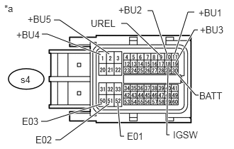
Disconnect the urea pump control ECU connector.
b.
Measure the resistance according to the value(s) in the table below.
- Standard Resistance:
Tester Connection Condition Specified Condition s4-52 (E01) - Body ground Always Below 1 Ω s4-51 (E02) - Body ground Always Below 1 Ω s4-50 (E03) - Body ground Always Below 1 Ω
c.
Measure the voltage according to the value(s) in the table below.
- Standard Voltage:
Tester Connection Condition Specified Condition s4-30 (BATT) - Body ground Always 11 to 14 V s4-11 (+BU1) - Body ground Battery positive (+) voltage applied to terminal s4-9 (UREL) 11 to 14 V s4-10 (+BU2) - Body ground Battery positive (+) voltage applied to terminal s4-9 (UREL) 11 to 14 V s4-19 (+BU3) - Body ground Battery positive (+) voltage applied to terminal s4-9 (UREL) 11 to 14 V s4-1 (+BU4) - Body ground Battery positive (+) voltage applied to terminal s4-9 (UREL) 11 to 14 V s4-2 (+BU5) - Body ground Battery positive (+) voltage applied to terminal s4-9 (UREL) 11 to 14 V s4-18 (IGSW) - Body ground Engine switch on (IG) 11 to 14 V
| *a | Front view of wire harness connector
(to Urea Pump Control ECU) |
OK
REPLACE UREA PUMP CONTROL ECU
NG
REPAIR OR REPLACE HARNESS OR CONNECTOR