Home › Vehicle Interior › LIGHTING (INT) › LIGHTING SYSTEM › 2015.06–2017.08
RM27T0E _58 Vehicle Interior _053732 LIGHTING (INT) _0261068 LIGHTING SYSTEM J

LIGHTING (INT)  LIGHTING SYSTEM  Overhead Console Illumination Light Circuit  


DESCRIPTION

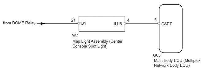
The main body ECU controls the center console spot light.

WIRING DIAGRAM
E284570E03
0.104,0.698 2.396,0.896 2.292,0.198 10 false from DOME Relay 2.448,1.125 2.76,1.323 0.313,0.198 10 false W7 2.458,1.323 4.25,1.698 1.792,0.375 10 false Map Light Assembly (Center Console Spot Light) 5.479,0.729 6.094,0.927 0.615,0.198 10 false CSPT 2.417,0.604 2.729,0.802 0.313,0.198 10 false 21 4.313,0.604 4.469,0.802 0.156,0.198 10 false 4 3.865,0.729 4.479,0.927 0.615,0.198 10 false ILLB 2.76,0.708 3.073,0.906 0.313,0.198 10 false B1 5.198,1.802 5.656,2 0.458,0.198 10 false G65 5.229,1.979 6.865,2.354 1.635,0.375 10 false Main Body ECU (Multiplex Network Body ECU) 5.24,0.594 5.396,0.792 0.156,0.198 10 false 5

CAUTION / NOTICE / HINT

NOTICE:

Inspect the fuses for circuits related to this system before performing the following inspection procedure.


PROCEDURE

1.PERFORM ACTIVE TEST USING INTELLIGENT TESTER (CENTER CONSOLE SPOT LIGHT)
a.

Using the intelligent tester, perform the Active Test (See page Vehicle Interior>LIGHTING (INT)>LIGHTING SYSTEM>DATA LIST / ACTIVE TEST).

Main Body
Tester Display Test Part Control Range Diagnostic Note
Cent Consol Spot LGT Center console spot light ON/OFF -

OK:

Center console spot light comes on.


OK

PROCEED TO NEXT SUSPECTED AREA SHOWN IN PROBLEM SYMPTOMS TABLE

NG

2.INSPECT MAP LIGHT ASSEMBLY
a.
E140936E78
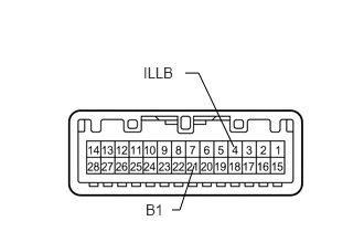
2.208,1.385 1.875,0.688 1.875,0.688 1.75,0.688 false 1.833,1.563 1.698,1.979 1.698,1.979 1.625,1.979 false 1.354,0.604 1.698,0.781 0.344,0.177 10 false ILLB 1.375,1.896 1.646,2.073 0.271,0.177 10 false B1

Remove the map light (See page Vehicle Interior>LIGHTING (INT)>ROOM LIGHT(for Front)>REMOVAL).


b.

Connect a positive (+) lead from the battery to terminal 21 (B1) and a negative (-) lead to terminal 4 (ILLB).


c.

Check that the center console spot light comes on.

OK:

Center console spot light comes on.


OK

3.CHECK HARNESS AND CONNECTOR (BATTERY - MAP LIGHT ASSEMBLY)

NG

3.CHECK HARNESS AND CONNECTOR (BATTERY - MAP LIGHT ASSEMBLY)
a.
U170569E01
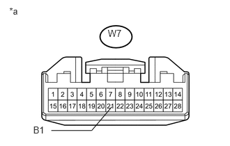
0.139,0.083 0.375,0.253 0.236,0.170 10 *a 1.611,0.418 1.871,0.581 0.260,0.163 10 W7 0.496,1.869 0.794,2.045 0.298,0.177 10 B1 1.671,1.6 1.369,1.956 1.369,1.956 0.767,1.956 false

Disconnect the W7 map light connector.


b.

Measure the voltage according to the value(s) in the table below.

Standard Voltage:
Tester Connection Condition Specified Condition
W7-21 (B1) - Body ground Battery saving control (interior light auto cut function) not operating 11 to 14 V


Text in Illustration
*a Front view of wire harness connector
(to Map Light Assembly)


OK

4.CHECK HARNESS AND CONNECTOR (MAP LIGHT ASSEMBLY - MAIN BODY ECU)

NG

REPAIR OR REPLACE HARNESS OR CONNECTOR

4.CHECK HARNESS AND CONNECTOR (MAP LIGHT ASSEMBLY - MAIN BODY ECU)
a.

Disconnect the W7 map light connector.


b.

Disconnect the G65 main body ECU connector.


c.

Measure the resistance according to the value(s) in the table below.

Standard Resistance:
Tester Connection Condition Specified Condition
W7-4 (ILLB) - G65-5 (CSPT) Always Below 1 Ω
W7-4 (ILLB) - Body ground Always 10 kΩ or higher


OK

REPLACE MAIN BODY ECU (MULTIPLEX NETWORK BODY ECU)

NG

REPAIR OR REPLACE HARNESS OR CONNECTOR