RM27T0E
_58
Vehicle Interior
_053733
METER / GAUGE / DISPLAY
_0261082
METER / GAUGE SYSTEM
J
METER / GAUGE / DISPLAY METER / GAUGE SYSTEM Odo/Trip Switch Malfunction
DESCRIPTION
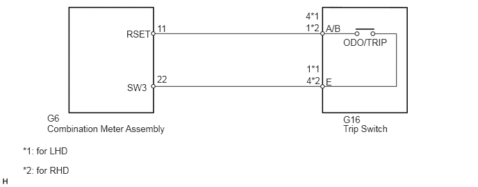
The meter CPU receives ODO/TRIP change switch signal from the light control rheostat via the direct line.
- HINT:
-
The whole light control rheostat should be replaced if the ODO/TRIP switch is malfunctioning.
WIRING DIAGRAM
1.896,0.427 2.417,0.667
0.521,0.24
10
false
RSET
4.885,0.344 5.156,0.49
0.271,0.146
10
false
A/B
5.146,0.552 5.865,0.698
0.719,0.146
10
false
ODO/TRIP
2.354,0.344 2.531,0.49
0.177,0.146
10
false
11
4.583,0.333 4.813,0.479
0.229,0.146
10
false
1*2
4.885,1.146 5.094,1.323
0.208,0.177
10
false
E
4.594,1.125 4.833,1.271
0.24,0.146
10
false
4*2
0.708,1.688 0.99,1.875
0.281,0.188
10
false
G6
5.146,1.708 5.438,1.854
0.292,0.146
10
false
G16
0.708,1.844 2.594,2.083
1.885,0.24
10
false
Combination Meter Assembly
5.146,1.844 5.865,2.031
0.719,0.188
10
false
Trip Switch
4.583,0.156 4.813,0.302
0.229,0.146
10
false
4*1
4.594,0.948 4.823,1.094
0.229,0.146
10
false
1*1
0.344,2.177 1.073,2.323
0.729,0.146
10
false
*1: for LHD
0.344,2.469 1.073,2.615
0.729,0.146
10
false
*2: for RHD
1.906,1.229 2.385,1.479
0.479,0.25
10
false
SW3
2.354,1.104 2.552,1.25
0.198,0.146
10
false
22
PROCEDURE
1.READ VALUE USING GTS (ODO/TRIP CHANGE SW)
a.
Using the GTS, read the Data List (See page Vehicle Interior>METER / GAUGE / DISPLAY>METER / GAUGE SYSTEM>DATA LIST / ACTIVE TEST).
| Tester Display | Measurement Item/Range | Normal Condition | Diagnostic Note |
|---|---|---|---|
| ODO/TRIP Change SW | ODO/TRIP change switch/OFF or ON | OFF: ODO/TRIP change switch released | - |
| ON: ODO/TRIP change switch pressed |
- OK:
The value displayed on the GTS changes with the actual ODO/TRIP change switch operation.
OK
REPLACE COMBINATION METER ASSEMBLY
NG
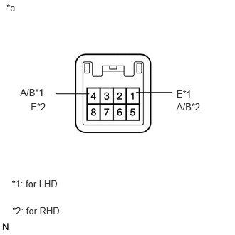
2.INSPECT TRIP SWITCH
2.INSPECT TRIP SWITCH
a.
0.095,0.034 0.302,0.204
0.207,0.170
10
*a
1.306,1.372 0.813,1.372
false
1.989,1.351 2.515,1.351
false
0.295,1.271 0.677,1.441
0.382,0.170
10
A/B*1
0.45,1.477 0.709,1.647
0.259,0.170
10
E*2
2.581,1.477 2.995,1.647
0.414,0.170
10
A/B*2
2.581,1.288 2.895,1.438
0.313,0.150
10
E*1
0.171,2.6 0.903,2.770
0.732,0.170
10
*1: for LHD
0.179,2.995 0.911,3.165
0.732,0.170
10
*2: for RHD
Disconnect the G16 trip switch connector.
b.
Inspect the ODO/TRIP switch
i.
Measure the resistance according to the value(s) in the table below.
- Standard Resistance:
for LHD Tester Connection Switch Condition Specified Condition 4 (A/B) - 1 (E) ODO/TRIP switch on (pushed) Below 1 Ω ODO/TRIP switch off (Not pushed) 1 MΩ or higher
for RHD Tester Connection Switch Condition Specified Condition 1 (A/B) - 4 (E) ODO/TRIP switch on (pushed) Below 1 Ω ODO/TRIP switch off (Not pushed) 1 MΩ or higher
OK
3.CHECK HARNESS AND CONNECTOR (COMBINATION METER ASSEMBLY - TRIP SWITCH)
NG
3.CHECK HARNESS AND CONNECTOR (COMBINATION METER ASSEMBLY - TRIP SWITCH)
a.
Disconnect the G6 combination meter assembly connector.
b.
Disconnect the G16 trip switch connector.
c.
Measure the resistance according to the value(s) in the table below.
- Standard Resistance:
for LHD Tester Connection Condition Specified Condition G6-11 (RSET) - G16-4 (A/B) Always Below 1 Ω G6-11 (RSET) - Body ground Always 10 kΩ or higher
for RHD Tester Connection Condition Specified Condition G6-11 (RSET) - G16-1 (A/B) Always Below 1 Ω G6-11 (RSET) - Body ground Always 10 kΩ or higher
OK
REPLACE COMBINATION METER ASSEMBLY
NG
REPAIR OR REPLACE HARNESS OR CONNECTOR