PRE-CRASH SAFETY PRE-CRASH SAFETY SYSTEM B2005 Short to B+ in Seat Belt Motor LH Circuit
DESCRIPTION
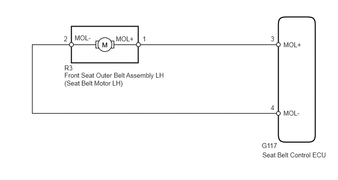
The seat belt control ECU receives collision information from the driving support ECU and skid control ECU via CAN communication and tightens the seat belt by operating the motor inside the front seat outer belt LH.
When DTC B2005 is stored, DTCs B2021, B2031, B2032 and B2035 are not stored.
| DTC Code | DTC Detection Condition | Trouble Area |
|---|---|---|
| B2005 | During the initial check or with the ignition switch ON, the seat belt motor LH circuit has a power supply short (the voltage at terminals MOL+ and MOL- is 8.5 V or higher) for 1 second or more. | ·
Front seat outer belt assembly LH ·
Harness or connector ·
Seat belt control ECU |
WIRING DIAGRAM
CAUTION / NOTICE / HINT
- CAUTION:
-
The pretensioner is built into the front seat outer belt assembly LH. Be sure to follow the correct inspection procedure, as failure to follow the correct procedure (such as inspection of incorrect connectors) may activate the pretensioner.
PROCEDURE
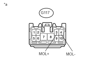
Disconnect the G117 ECU connector.
Measure the voltage according to the value(s) in the table below.
- Standard Voltage:
Tester Connection Switch Condition Specified Condition G117-3 (MOL+) - Body ground Ignition switch ON Below 1 V G117-4 (MOL-) - Body ground
| *a | Front view of wire harness connector
(to Seat Belt Control ECU) |
OK
NG
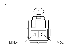
Disconnect the R3 belt connector.
Disconnect the G117 ECU connector.
Measure the voltage according to the value(s) in the table below.
- Standard Voltage:
Tester Connection Switch Condition Specified Condition R3-1 (MOL+) - Body ground Ignition switch ON Below 1 V R3-2 (MOL-) - Body ground
| *a | Front view of wire harness connector
(to Front Seat Outer Belt Assembly LH) |
OK
NG