PRE-CRASH SAFETY PRE-CRASH SAFETY SYSTEM U0235 Lost Communication with Cruise Control Front Distance Range Sensor
DESCRIPTION
The millimeter wave radar sensor assembly and driving support ECU transit the data for the general vehicle control diagnosis function along the communication line. The millimeter wave radar sensor assembly transmits information about the vehicle in front to the driving support ECU.
| DTC Code | DTC Detection Condition | Trouble Are |
|---|---|---|
| U0235 | When the ignition switch is ON, a communication error between the millimeter wave radar sensor assembly and driving support ECU is detected for 1 second. | ·
Harness or connector ·
Millimeter wave radar sensor assembly ·
Driving support ECU |
WIRING DIAGRAM
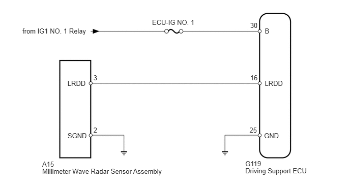
CAUTION / NOTICE / HINT
- NOTICE:
- ·
Inspect the fuses for circuits related to this system before performing the following inspection procedure.
·Confirm that the connector is securely connected, as a partially connected connector may be the cause of this DTC being output.
PROCEDURE
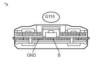
Disconnect the G119 ECU connector.
Measure the voltage according to the value(s) in the table below.
- Standard Voltage :
Tester Connection Switch Condition Specified Condition G119-30 (B) - Body ground Ignition switch ON 11 to 14 V Ignition switch off Below 1 V
Measure the resistance according to the value(s) in the table below.
- Standard Resistance:
Tester Connection Condition Specified Condition G119-25 (GND) - Body ground Always Below 1 Ω
| *a | Front view of wire harness connector
(to Driving Support ECU) |
OK
NG
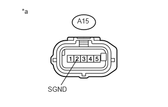
Disconnect the A15 sensor connector.
Measure the resistance according to the value(s) in the table below.
- Standard Resistance:
Tester Connection Condition Specified Condition A15-2 (SGND) - Body ground Always Below 1 Ω
| *a | Front view of wire harness connector
(to Millimeter Wave Radar Sensor Assembly) |
OK
NG
Disconnect the G119 ECU connector.
Disconnect the A15 sensor connector.
Measure the resistance according to the value(s) in the table below.
- Standard Resistance:
Tester Connection Condition Specified Condition G119-16 (LRDD) - A15-3 (LRDD) Always Below 1 Ω G119-16 (LRDD) - Body ground Always 10 kΩ or higher
OK
NG
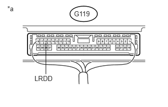
Disconnect the A15 sensor connector.
Measure the voltage according to the value(s) in the table below.
- Standard Voltage:
Tester Connection Switch Condition Specified Condition G119-16 (LRDD) - Body ground Ignition switch ON 4.5 to 5.5 V
| *a | Component without harness connected
(Driving Support ECU) |
OK
NG
Replace the millimeter wave radar sensor assembly (See page Engine / Hybrid System>CRUISE CONTROL>MILLIMETER WAVE RADAR SENSOR>REMOVAL).
NEXT
Adjust the millimeter wave radar sensor assembly (See page Engine / Hybrid System>CRUISE CONTROL>MILLIMETER WAVE RADAR SENSOR>ADJUSTMENT).
NEXT
Clear the DTCs (See page Vehicle Interior>PRE-CRASH SAFETY>PRE-CRASH SAFETY SYSTEM>DTC CHECK / CLEAR).
Check for DTCs (See page Vehicle Interior>PRE-CRASH SAFETY>PRE-CRASH SAFETY SYSTEM>DTC CHECK / CLEAR).
- OK:
DTC U0235 is not output.
OK
NG