PRE-CRASH SAFETY PRE-CRASH SAFETY SYSTEM U1104 Lost Communication with Driving Support ECU
DESCRIPTION
| DTC Code | DTC Detection Condition | Trouble Are |
|---|---|---|
| U1104 | When the ignition switch is ON, a communication error between the millimeter wave radar sensor assembly and driving support ECU is detected for 1 second. | ·
Harness or connector ·
Millimeter wave radar sensor assembly ·
Driving support ECU |
| U1104 | When the ignition switch is ON, communication stops between the seat belt control ECU and driving support ECU for 1 second or more. | ·
Seat belt control ECU ·
CAN communication system ·
Driving support ECU |
WIRING DIAGRAM
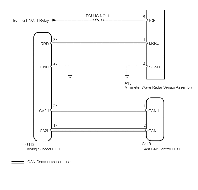
CAUTION / NOTICE / HINT
- NOTICE:
- ·
When the millimeter wave radar sensor assembly is replaced with a new one, adjustment of the radar sensor beam axis must be performed (See page Engine / Hybrid System>CRUISE CONTROL>MILLIMETER WAVE RADAR SENSOR>ADJUSTMENT).
·Inspect the fuses for circuits related to this system before performing the following inspection procedure.
·Confirm that the connector is securely connected, as a partially connected connector may be the cause of this DTC being output.
PROCEDURE
Clear the DTCs (See page Vehicle Interior>PRE-CRASH SAFETY>PRE-CRASH SAFETY SYSTEM>DTC CHECK / CLEAR).
Check for DTCs (See page Vehicle Interior>PRE-CRASH SAFETY>PRE-CRASH SAFETY SYSTEM>DTC CHECK / CLEAR).
| Result | Proceed to |
|---|---|
| DTC U1104 is not output | A |
| DTC U1104 is output from driving support ECU (Pre-Crash 2) | B |
| DTC U1104 is output from seat belt control ECU (Pre-Crash) | C |
A
(See pageGeneral>INTRODUCTION>HOW TO TROUBLESHOOT ECU CONTROLLED SYSTEMS>HOW TO PROCEED WITH TROUBLESHOOTING)
B
C
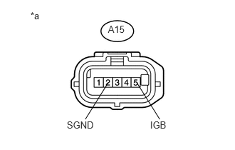
Disconnect the A15 sensor connector.
Measure the voltage according to the value(s) in the table below.
- Standard Voltage :
Tester Connection Switch Condition Specified Condition A15-5 (IGB) - Body ground Ignition switch ON 11 to 14 V Ignition switch off Below 1 V
Measure the resistance according to the value(s) in the table below.
- Standard Resistance:
Tester Connection Condition Specified Condition A15-2 (SGND) - Body ground Always Below 1 Ω
| *a | Front view of wire harness connector
(to Millimeter Wave Radar Sensor Assembly) |
OK
NG
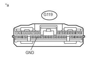
Disconnect the G119 ECU connector.
Measure the resistance according to the value(s) in the table below.
- Standard Resistance:
Tester Connection Condition Specified Condition G119-25 (GND) - Body ground Always Below 1 Ω
| *a | Front view of wire harness connector
(to Driving Support ECU) |
OK
NG
Disconnect the A15 sensor connector.
Disconnect the G119 ECU connector.
Measure the resistance according to the value(s) in the table below.
- Standard Resistance:
Tester Connection Condition Specified Condition A15-4 (LRRD) - G119-38 (LRRD) Always Below 1 Ω A15-4 (LRRD) - Body ground Always 10 kΩ or higher
OK
NG
Replace the driving support ECU (See page Engine / Hybrid System>CRUISE CONTROL>DRIVING SUPPORT ECU>REMOVAL).
NEXT
Clear the DTCs (See page Vehicle Interior>PRE-CRASH SAFETY>PRE-CRASH SAFETY SYSTEM>DTC CHECK / CLEAR).
Check for DTCs (See page Vehicle Interior>PRE-CRASH SAFETY>PRE-CRASH SAFETY SYSTEM>DTC CHECK / CLEAR).
- OK:
DTC U1104 is not output.
OK
NG
Select "Bus Check" from the "System Select" screen on the intelligent tester.
Select "Communication Malfunction DTC" from the "Bus Check" screen, and then select "Enter".
| Result | Proceed to |
|---|---|
| CAN DTC is not output | A |
| CAN DTC is output (for LHD with Entry and Start System) | B |
| CAN DTC is output (for LHD without Entry and Start System) | C |
| CAN DTC is output (for RHD with Entry and Start System) | D |
| CAN DTC is output (for RHD without Entry and Start System) | E |
A
(See pageGeneral>INTRODUCTION>HOW TO TROUBLESHOOT ECU CONTROLLED SYSTEMS>HOW TO PROCEED WITH TROUBLESHOOTING)
B
C
D
E