INTERIOR PANELS / TRIM ROOF HEADLINING(for 5 Door) REASSEMBLY
CAUTION / NOTICE / HINT
- HINT:
- ·
Use the same procedure for RHD and LHD vehicles.
·The procedure listed below is for LHD vehicles.
PROCEDURE

 86101J
1.INSTALL NO. 2 ANTENNA CORD SUB-ASSEMBLY
82171
2.INSTALL NO. 1 ROOF WIRE
Apply butyl tape to the roof headlining so that the tape is aligned with the wire harness marking as shown in the illustration.
- HINT:
-
Use butyl tape that has a width of 10 mm (0.394 in.).
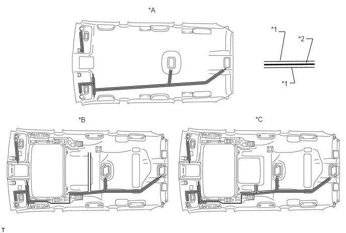
| *A | w/o Sliding Roof | *B | w/ Sliding Roof |
| *C | w/ Rear Seat Entertainment System | - | - |
| *1 | Wire Harness Marking | *2 | Butyl Tape |
Align the No. 1 roof wire with the wire harness installation points as shown in the illustration and attach it to the roof headlining to install it.
- HINT:
-
Be sure to securely attach the roof wire so that it is not twisted.
Attach each clamp.
- HINT:
-
Make sure the EC mirror wire harness (w/ EC Mirror) and rain sensor wire harness (w/ Rain Sensor) are securely set into the cutouts of the roof headlining.
Turn the visor connectors approximately 90° clockwise to install them to the roof headlining.
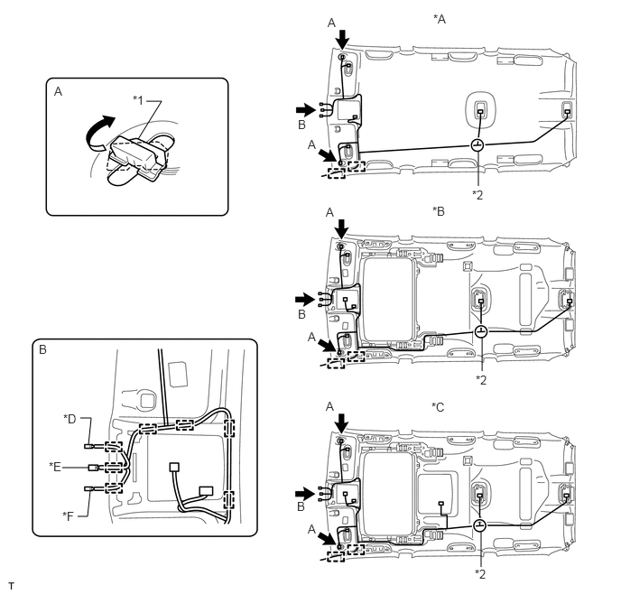
| *A | w/o Sliding Roof | *B | w/ Sliding Roof |
| *C | w/ Rear Seat Entertainment System | *D | w/ Rain Sensor, for LHD |
| *E | w/ EC Mirror | *F | w/ Rain Sensor, for RHD |
| *1 | Visor Connector | *2 | Wire Harness Installation Point |
81340J
3.INSTALL VANITY LIGHT ASSEMBLY LH
Attach the 3 claws to install the vanity light.
81340H
4.INSTALL VANITY LIGHT ASSEMBLY RH
- HINT:
-
Use the same procedure described for the LH side.
63344
5.INSTALL NO. 4 ROOF SILENCER PAD (w/o Sliding Roof)
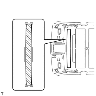
Align the No. 4 roof silencer pad with the markings on the roof headlining and install the No. 4 roof silencer pad to the position shown in the illustration using hot-melt glue or double-sided tape.
63343
6.INSTALL NO. 3 ROOF SILENCER PAD
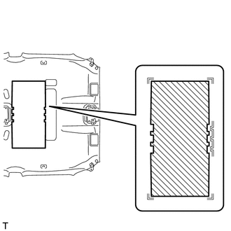
Align the No. 3 roof silencer pad with the markings on the roof headlining and install the No. 3 roof silencer pad to the position shown in the illustration using hot-melt glue or double-sided tape.
63342
7.INSTALL NO. 2 ROOF SILENCER PAD (w/o Sliding Roof)
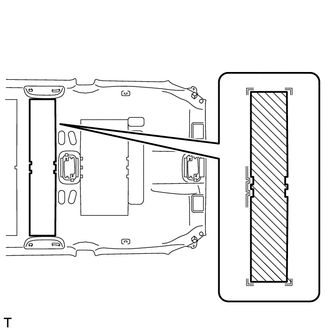
Align the No. 2 roof silencer pad with the markings on the roof headlining and install the No. 2 roof silencer pad to the position shown in the illustration using hot-melt glue or double-sided tape.
63341
8.INSTALL NO. 1 ROOF SILENCER PAD (w/o Sliding Roof)
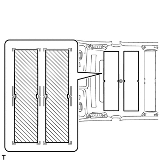
Align the No. 1 roof silencer pad with the markings on the roof headlining and install the No. 1 roof silencer pad to the position shown in the illustration using hot-melt glue or double-sided tape.
62985A
9.INSTALL ROOF SIDE AIR OUTLET REGISTER (w/ Rear Air Conditioning System)
- HINT:
-
Use the same procedure for all roof side air outlet registers.
Attach the 6 claws to install the roof side air outlet register.