AUDIO / VIDEO RADIO ANTENNA CORD INSTALLATION
PROCEDURE

 86101J
1.INSTALL NO. 2 ANTENNA CORD SUB-ASSEMBLY (for 5 Door)
w/o Sliding Roof:
Apply new double-sided tape as shown in the illustration.
- HINT:
-
Attach double-sided tape to the hatched areas shown in the illustration below.
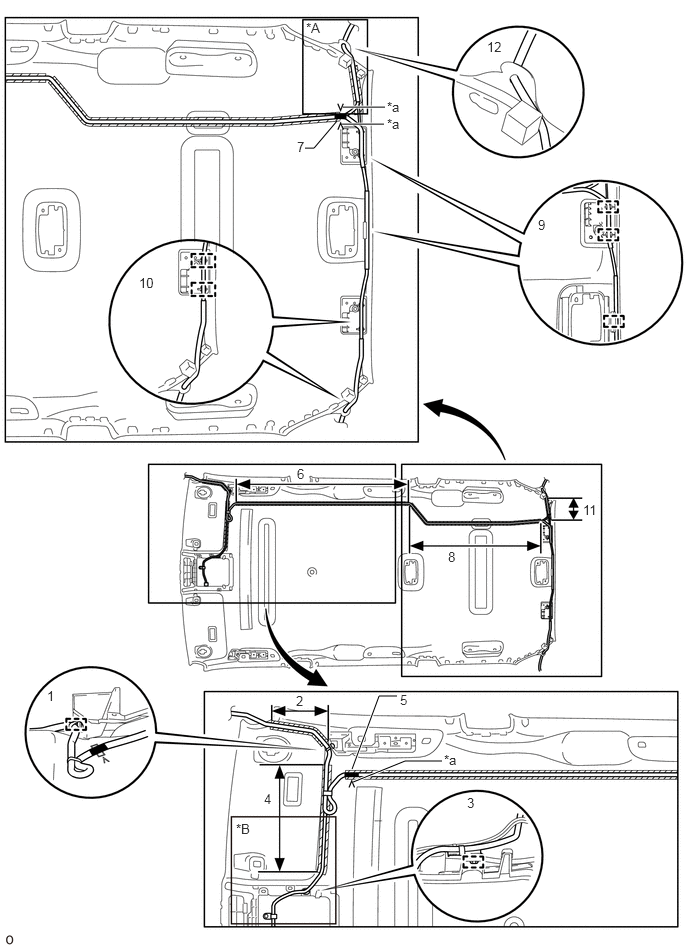
| *A | for Diversity | *B | for Diversity, w/ Digital Audio Broadcasting |
| *a | V Mark | - | - |

|
Marking Tape | 
|
Double-sided Tape |
Attach the clamp in the part of the illustration labeled 1.
Align the antenna cord with the marking in the part of the illustration labeled 2 and attach it to the double-sided tape.
Attach the clamp in the part of the illustration labeled 3.
Align the antenna cord with the marking in the part of the illustration labeled 4 and attach it to the double-sided tape.
Align the marking tape on the antenna cord with the V mark on the roof headlining in the part of the illustration labeled 5.
Align the antenna cord with the marking in the part of the illustration labeled 6 and attach it to the double-sided tape.
Align the marking tape on the antenna cord with the V mark on the roof headlining in the part of the illustration labeled 7.
While gathering the slack in the antenna cord in the part of the illustration labeled 8, align the antenna cord with the marking and attach it to the double-sided tape.
Attach the clamps in the parts of the illustration labeled 9 and 10.
Align the antenna cord with the marking in the part of the illustration labeled 11 and attach it to the double-sided tape.
Attach the antenna cord to the notches in the roof headlining in the parts of the illustration labeled 10 and 12.
w/ Sliding Roof:
Apply new double-sided tape as shown in the illustration.
- HINT:
-
Attach double-sided tape to the hatched areas shown in the illustration below.
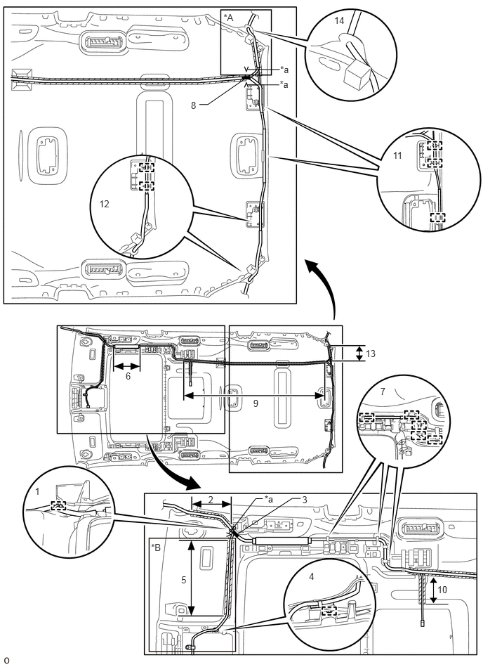
| *A | for Diversity | *B | for Diversity, w/ Digital Audio Broadcasting |
| *a | V Mark | - | - |
|
|
Marking Tape |
|
Double-sided Tape |
Attach the clamp in the part of the illustration labeled 1.
Align the antenna cord with the marking in the part of the illustration labeled 2 and attach it to the double-sided tape.
Align the marking tape on the antenna cord with the V mark on the roof headlining in the part of the illustration labeled 3.
Attach the clamp in the part of the illustration labeled 4.
Align the antenna cord with the marking in the part of the illustration labeled 5 and attach it to the double-sided tape.
Align the antenna cord with the marking in the part of the illustration labeled 6 and attach it to the double-sided tape.
Attach the clamps in the part of the illustration labeled 7.
Align the marking tape on the antenna cord with the V mark on the roof headlining in the part of the illustration labeled 8.
While gathering the slack in the antenna cord in the part of the illustration labeled 9, align the antenna cord with the marking and attach it to the double-sided tape.
Align the antenna cord with the marking in the part of the illustration labeled 10 and attach it to the double-sided tape.
Attach the clamps in the parts of the illustration labeled 11 and 12.
Align the antenna cord with the marking in the part of the illustration labeled 13 and attach it to the double-sided tape.
Attach the antenna cord to the notches in the roof headlining in the parts of the illustration labeled 12 and 14.
86101J
2.INSTALL NO. 2 ANTENNA CORD SUB-ASSEMBLY (for 3 Door)
w/o Sliding Roof:
Apply new double-sided tape as shown in the illustration.
- HINT:
-
Attach double-sided tape to the hatched areas shown in the illustration below.
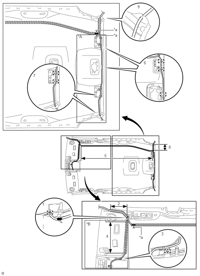
| *A | for Diversity | *B | for Diversity, w/ Digital Audio Broadcasting |
| *a | V Mark | - | - |
|
|
Marking Tape |
|
Double-sided Tape |
Attach the clamp in the part of the illustration labeled 1.
Align the antenna cord with the marking in the part of the illustration labeled 2 and attach it to the double-sided tape.
Attach the clamp in the part of the illustration labeled 3.
Align the antenna cord with the marking in the part of the illustration labeled 4 and attach it to the double-sided tape.
Align the marking tape on the antenna cord with the V marks on the front and rear of the roof headlining, and then align the antenna cord with the marking in the part of the illustration labeled 5 and attach it to the double-sided tape.
Attach the clamps in the parts of the illustration labeled 6 and 7.
Align the antenna cord with the marking in the part of the illustration labeled 8 and attach it to the double-sided tape.
Attach the antenna cord to the notches in the roof headlining in the parts of the illustration labeled 7 and 9.
w/ Sliding Roof:
Apply new double-sided tape as shown in the illustration.
- HINT:
-
Attach double-sided tape to the hatched areas shown in the illustration below.
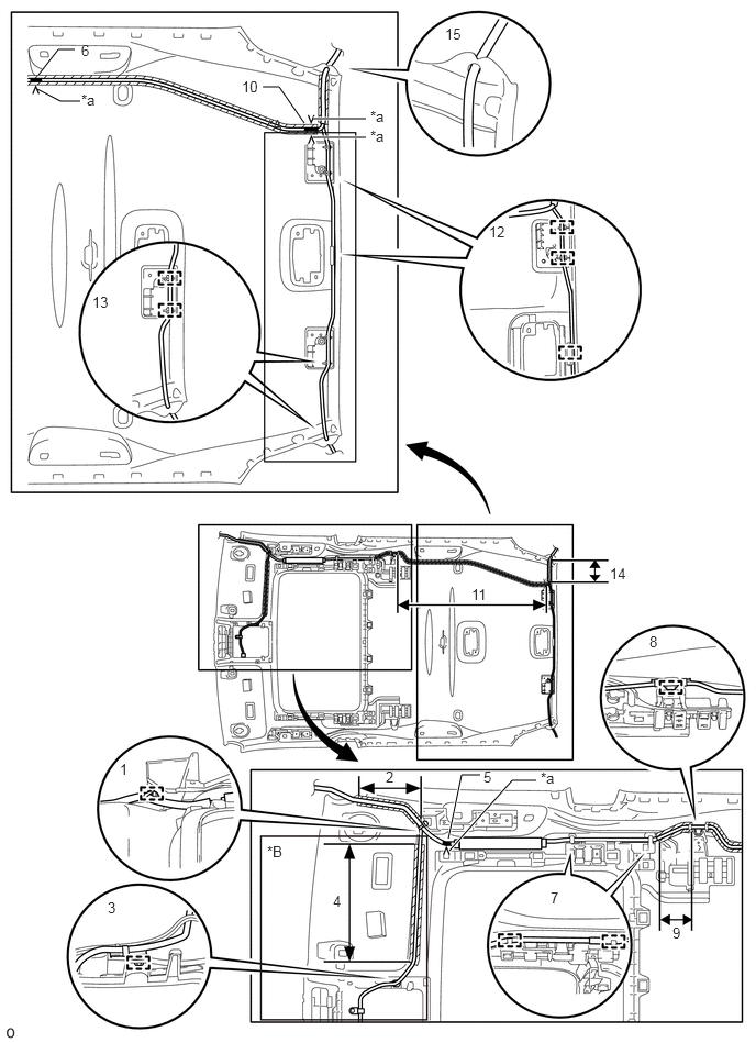
| *A | for Diversity | *B | for Diversity, w/ Digital Audio Broadcasting |
| *a | V Mark | - | - |
|
|
Marking Tape |
|
Double-sided Tape |
Attach the clamp in the part of the illustration labeled 1.
Align the antenna cord with the marking in the part of the illustration labeled 2 and attach it to the double-sided tape.
Attach the clamp in the part of the illustration labeled 3.
Align the antenna cord with the marking in the part of the illustration labeled 4 and attach it to the double-sided tape.
Align the marking tape on the antenna cord with the V marks on the roof headlining in the part of the illustration labeled 5 and 6.
Attach the clamps in the part of the illustration labeled 7.
Attach the clamp in the part of the illustration labeled 8.
Align the antenna cord with the marking in the part of the illustration labeled 9 and attach it to the double-sided tape.
Align the marking tape on the antenna cord with the V marks on the roof headlining in the part of the illustration labeled 10.
While gathering the slack in the antenna cord in the part of the illustration labeled 11, align the antenna cord with the marking and attach it to the double-sided tape.
Attach the clamps in the parts of the illustration labeled 12 and 13.
Align the antenna cord with the marking in the part of the illustration labeled 14 and attach it to the double-sided tape.
Attach the antenna cord to the notches in the roof headlining in the parts of the illustration labeled 13 and 15.
63310
3.INSTALL ROOF HEADLINING ASSEMBLY
for 5 Door:
(See page Vehicle Interior>INTERIOR PANELS / TRIM>ROOF HEADLINING (for 5 Door)>INSTALLATION)
for 3 Door:
(See page Vehicle Interior>INTERIOR PANELS / TRIM>ROOF HEADLINING (for 3 Door)>INSTALLATION)
4.CONNECT CABLE TO NEGATIVE BATTERY TERMINAL
- NOTICE:
-
When disconnecting the cable, some systems need to be initialized after the cable is reconnected (See page General>INTRODUCTION>REPAIR INSTRUCTION>INITIALIZATION).