Home › Vehicle Exterior › LIGHTING (EXT) › LIGHTING SYSTEM › 2015.06–2017.08
RM27T0E _59 Vehicle Exterior _053747 LIGHTING (EXT) _0261275 LIGHTING SYSTEM J

LIGHTING (EXT)  LIGHTING SYSTEM  Headlight (HI-BEAM) Circuit  


DESCRIPTION

The main body ECU receives headlight dimmer switch information signals and illuminates the high beam headlights.

WIRING DIAGRAM
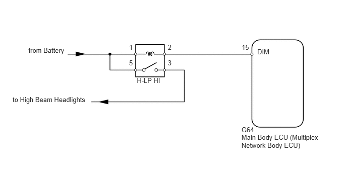
E199761E05
4.987,2.608 5.301,2.764 0.313,0.156 10 G64 4.987,2.765 6.720,3.132 1.732,0.367 10 Main Body ECU (Multiplex Network Body ECU) 4.991,0.891 5.202,1.061 0.211,0.170 10 15 5.313,0.986 5.733,1.156 0.420,0.170 10 DIM 2.826,1.582 3.417,1.752 0.591,0.170 10 H-LP HI 3.465,0.897 3.621,1.062 0.156,0.165 10 2 2.666,0.897 2.822,1.062 0.156,0.165 10 1 3.465,1.223 3.621,1.389 0.156,0.165 10 3 2.666,1.223 2.822,1.389 0.156,0.165 10 5 0.587,0.962 1.455,1.164 0.869,0.202 10 from Battery 0.26,1.976 1.878,2.160 1.619,0.184 10 to High Beam Headlights

CAUTION / NOTICE / HINT

NOTICE:

Inspect the fuses and bulbs for circuits related to this system before performing the following inspection procedure.


PROCEDURE

1.PERFORM ACTIVE TEST USING INTELLIGENT TESTER (HEADLIGHT)
a.

Using the intelligent tester, perform the Active Test (See page Vehicle Exterior>LIGHTING (EXT)>LIGHTING SYSTEM>DATA LIST / ACTIVE TEST).

Main Body
Tester Display Test Part Control Range Diagnostic Note
Head Light Hi Headlight dimmer relay ON/OFF -

OK:

Relay operates (high beam headlights illuminate).


OK

REPLACE MAIN BODY ECU (MULTIPLEX NETWORK BODY ECU)

NG

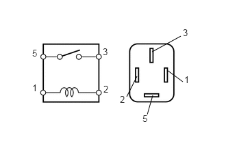
2.INSPECT HEADLIGHT RELAY (H-LP HI)
a.
E108359E22
2.313,0.792 2.75,0.552 false 2.323,1.458 2.24,1.75 false 2.083,1.167 1.927,1.479 false 2.542,1.073 2.781,1.25 false 0.49,0.729 0.615,0.927 0.125,0.198 10 false 5 0.49,1.26 0.615,1.458 0.125,0.198 10 false 1 2.781,0.417 2.906,0.615 0.125,0.198 10 false 3 2.802,1.135 2.927,1.333 0.125,0.198 10 false 1 2.167,1.729 2.302,1.927 0.135,0.198 10 false 5 1.823,1.438 1.948,1.635 0.125,0.198 10 false 2 1.573,1.281 1.698,1.479 0.125,0.198 10 false 2 1.563,0.708 1.698,0.906 0.135,0.198 10 false 3

Remove the headlight relay from the engine room relay block.


b.

Measure the resistance according to the value(s) in the table below.

Standard Resistance:
Tester Connection Condition Specified Condition
3 - 5 Battery voltage not applied between terminals 1 and 2 10 kΩ or higher
3 - 5 Battery voltage applied between terminals 1 and 2 Below 1 Ω


OK

3.CHECK HARNESS AND CONNECTOR (HEADLIGHT RELAY [H-LP HI] - BATTERY)

NG

REPLACE HEADLIGHT RELAY (H-LP HI)

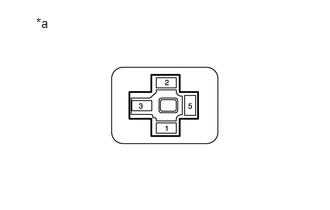
3.CHECK HARNESS AND CONNECTOR (HEADLIGHT RELAY [H-LP HI] - BATTERY)
a.
E199762E01
0.375,0.153 0.586,0.323 0.211,0.170 10 *a

Remove the headlight relay from the engine room relay block.


b.

Measure the voltage according to the value(s) in the table below.

Standard Voltage:
Tester Connection Condition Specified Condition
Headlight dimmer relay terminal 1 - Body ground Always 11 to 14 V
Headlight dimmer relay terminal 5 - Body ground


Text in Illustration
*a Front view of wire harness connector
(to Headlight Dimmer Relay)


OK

4.CHECK HARNESS AND CONNECTOR (HEADLIGHT RELAY [H-LP HI] - MAIN BODY ECU AND BODY GROUND)

NG

REPAIR OR REPLACE HARNESS OR CONNECTOR

4.CHECK HARNESS AND CONNECTOR (HEADLIGHT RELAY [H-LP HI] - MAIN BODY ECU AND BODY GROUND)
a.

Remove the headlight relay from the engine room relay block.


b.

Disconnect the G64 main body ECU connector.


c.

Measure the resistance according to the value(s) in the table below.

Standard Resistance:
Tester Connection Condition Specified Condition
Headlight dimmer relay terminal 2 - G64-15 (DIM) Always Below 1 Ω
G64-15 (DIM) - Body ground Always 10 kΩ or higher


OK

PROCEED TO NEXT SUSPECTED AREA SHOWN IN PROBLEM SYMPTOMS TABLE

NG

REPAIR OR REPLACE HARNESS OR CONNECTOR