WIPER / WASHER FRONT WIPER MOTOR INSTALLATION
CAUTION / NOTICE / HINT
- HINT:
- ·
Use the same procedure as for the LHD and RHD vehicles.
·The procedure listed below is for the LHD vehicles.
PROCEDURE

 82375B
1.INSTALL WIPER MOTOR WIRE
Attach the claw to install the wiper motor wire.
85110
2.INSTALL WINDSHIELD WIPER MOTOR ASSEMBLY
Using a T30 "TORX" socket wrench, install the wiper motor assembly with the 2 bolts.
- Torque:
- 7.5 N*m (76 kgf*cm, 66 in.*lbf)
Connect the connector.
w/o Spring:
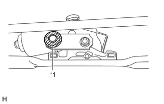
| *1 | Crank Arm Pivot |

|
MP grease |
Apply MP grease to the crank arm pivot of the front wiper crank.
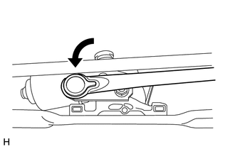
Connect the windshield wiper link rod to the crank arm pivot of the front wiper crank.
85012A
3.INSTALL FRONT WIPER CRANK SUB-ASSEMBLY (for RHD, w/ Spring)
Check the automatic stop position.
Check that the motor stops automatically at the automatic stop position.
Click hereVehicle Exterior>WIPER / WASHER>FRONT WIPER MOTOR>INSPECTION
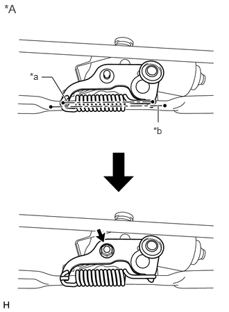
| *A | Front Wiper Crank Set Position |
| *a | Center Line of Crank Arm Spring |
| *b | Center Line of Wiper Link Stay |
Install the front wiper crank sub-assembly to the windshield wiper motor assembly with the nut so that center lines of the crank arm spring and wiper link stay are parallel.
- Torque:
- 8.5 N*m (87 kgf*cm, 6 ft.*lbf)
- HINT:
-
Hold the front wiper crank sub-assembly by hand when tightening the nut.
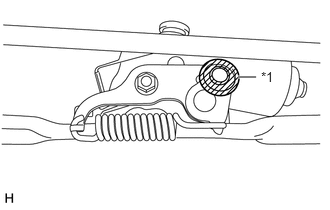
| *1 | Crank Arm Pivot |
|
|
MP grease |
Apply MP grease to the crank arm pivot of the front wiper crank sub-assembly.
Connect the windshiele wiper link rod of the windshield wiper link to the front wiper crank sub-assembly.
4.INSTALL WINDSHIELD WIPER MOTOR AND LINK
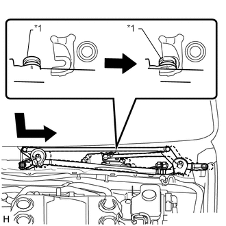
| *1 | Grommet |
Attach the grommet as shown in the illustration.
- NOTICE:
-
Be careful not to damage the windshield when installing the windshield wiper motor and link.
Install the windshield wiper motor and link with the 2 bolts.
- Torque:
- 7.0 N*m (71 kgf*cm, 62 in.*lbf)
Connect the connector.
Attach the clamp.
55781E
5.INSTALL COWL TOP VENTILATOR LOUVER SUB-ASSEMBLY
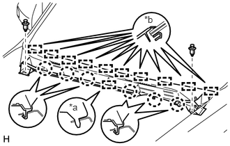
| *a | Guide (A) |
| *b | Guide (B) |
Attach the 10 guides (B).
Attach the 6 claws and guide (A) as shown in the illustration.
Install the cowl top ventilator louver sub-assembly with the 2 clips.
55784B
6.INSTALL CENTER NO. 2 COWL TOP VENTILATOR LOUVER
Attach the 2 claws and 3 guides to install the center No. 2 cowl top ventilator louver.
53383
7.INSTALL HOOD TO COWL TOP SEAL
Attach the 2 clips and 7 claws to install the hood to cowl top seal.
8.INSTALL FRONT WIPER ARM AND BLADE ASSEMBLY RH
Operate the wiper and stop the windshield wiper motor assembly at the automatic stop position.
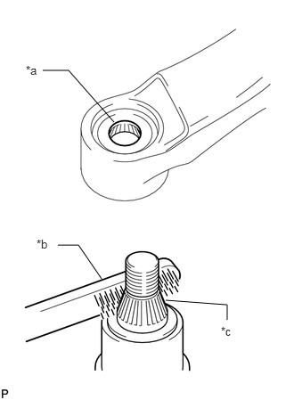
| *a | Wiper Arm Serration |
| *b | Wire Brush |
| *c | Wiper Pivot Serration |
When reusing the front wiper arm and blade assembly RH:
Clean the wiper arm serrations.
Clean the wiper pivot serrations.
- NOTICE:
-
Do not grind the wiper arm serrations excessively.
Turn the ignition switch to ON (IG).
Operate the wiper switch and stop the windshield wiper motor assembly at the automatic stop (park) position.
Turn the ignition switch off.
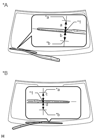
| *A | for LHD |
| *B | for RHD |
| *1 | Ceramic Dot |
| *a | Upper Limit |
| *b | Lower Limit |
Install the front wiper arm and blade assembly RH with the nut to the position shown in the illustration.
- Torque:
- 25 N*m (255 kgf*cm, 18 ft.*lbf)
| Area | Standard Condition |
|---|---|
| a | 7.5 mm (0.295 in.) |
| b | 7.5 mm (0.295 in.) |
| c | 7.5 mm (0.295 in.) |
| d | 7.5 mm (0.295 in.) |
- HINT:
- ·
Hold the wiper arm by hand while tightening the nut.
·Raise and lower the wiper arm a few times to confirm that it has settled to the specified position.
9.INSTALL FRONT WIPER ARM AND BLADE ASSEMBLY LH
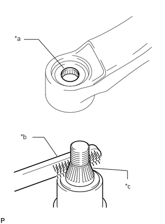
| *a | Wiper Arm Serration |
| *b | Wire Brush |
| *c | Wiper Pivot Serration |
When reusing the front wiper arm and blade assembly LH:
Clean the wiper arm serrations.
Clean the wiper pivot serrations.
- NOTICE:
-
Do not grind the wiper arm serrations excessively.
Turn the ignition switch to ON (IG).
Operate the wiper switch and stop the windshield wiper motor assembly at the automatic stop (park) position.
Turn the ignition switch off.
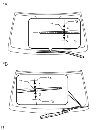
| *A | for LHD |
| *B | for RHD |
| *1 | Ceramic Dot |
| *a | Upper Limit |
| *b | Lower Limit |
Install the front wiper arm and blade assembly LH with the nut to the position shown in the illustration.
- Torque:
- 25 N*m (255 kgf*cm, 18 ft.*lbf)
| Area | Standard Condition |
|---|---|
| a | 7.5 mm (0.295 in.) |
| b | 7.5 mm (0.295 in.) |
| c | 7.5 mm (0.295 in.) |
| d | 7.5 mm (0.295 in.) |
- HINT:
- ·
Hold the wiper arm by hand while tightening the nut.
·Raise and lower the wiper arm a few times to confirm that it has settled to the specified position.
Operate the front wipers while spraying washer fluid on the windshield glass. Make sure that the front wipers function properly and there is no interference with the vehicle body.
85192
10.INSTALL WINDSHIELD WIPER ARM COVER
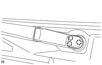
Attach the 3 claws to install the windshield wiper arm cover.
- HINT:
-
Use the same procedure for the RH side and LH side.
53867H
11.INSTALL FRONT FENDER TO COWL SIDE SEAL LH
Attach the 3 claws and guide to install the front fender to cowl side seal LH.
53866J
12.INSTALL FRONT FENDER TO COWL SIDE SEAL RH
- HINT:
-
Use the same procedure for the LH side.
53828J
13.INSTALL FRONT FENDER SIDE PANEL PROTECTOR LH
Attach the 3 clips and guide to install the front fender side panel protector LH.
53827K
14.INSTALL FRONT FENDER SIDE PANEL PROTECTOR RH
- HINT:
-
Use the same procedure for the LH side.
53292A
15.INSTALL UPPER RADIATOR SUPPORT SEAL
16.CONNECT CABLE TO NEGATIVE BATTERY TERMINAL
- NOTICE:
-
When disconnecting the cable, some systems need to be initialized after the cable is reconnected.
-
Click hereGeneral>INTRODUCTION>REPAIR INSTRUCTION>INITIALIZATION