Home › Drivetrain › AXLE AND DIFFERENTIAL › DIFFERENTIAL SYSTEM (w/ Differential Lock) › 2017.08–2021.06
RM27T0E _52 Drivetrain _053705 AXLE AND DIFFERENTIAL _0326415 DIFFERENTIAL SYSTEM(w/ Differential Lock) C

AXLE AND DIFFERENTIAL  DIFFERENTIAL SYSTEM(w/ Differential Lock)  P17C2  Rear Differential Lock Shift Motor Circuit Open  


DESCRIPTION

This DTC is output when an open circuit in the differential lock shift motor drive circuit is detected.

DTC No. DTC Detection Condition
1.

Diagnosis Condition

2.

Malfunction Status

3.

Malfunction Time

4.

Other


Trouble Area
P17C2
1.

When rear differential is switching between free and lock (differential lock shift motor operating) with ignition switch turned to ON

2.

Open circuit in the differential lock shift motor drive circuit

3.

0.03 seconds or more

4.

1 trip detection logic


·

Wire harness and connector

·

4 wheel drive control ECU

·

Differential lock shift actuator


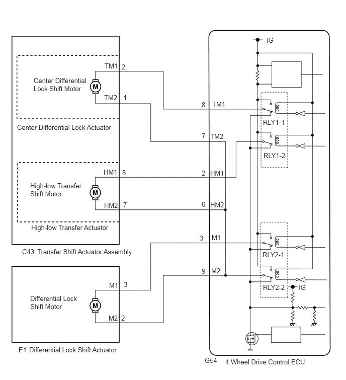
WIRING DIAGRAM

C386010E05
0.698,1.583 1.802,2.063 1.104,0.479 10 false Center Differential Lock Shift Motor 0.354,2.552 2.365,2.792 2.01,0.24 10 false Center Differential Lock Actuator 0.625,3.76 1.698,4.208 1.073,0.448 10 false High-low Transfer Shift Motor 2.167,1.281 2.625,1.479 0.458,0.198 10 false TM1 2.521,1.302 2.677,1.5 0.156,0.198 10 false 2 4.177,2.083 4.333,2.281 0.156,0.198 10 false 8 4.396,2.073 4.854,2.271 0.458,0.198 10 false TM1 5.448,2.448 6.365,2.646 0.917,0.198 10 false RLY1-1 5.521,0.75 5.833,0.948 0.313,0.198 10 false IG 5.458,3.135 6.375,3.333 0.917,0.198 10 false RLY1-2 4.354,2.74 4.813,2.938 0.458,0.198 10 false TM2 4.177,2.729 4.333,2.927 0.156,0.198 10 false 7 2.156,1.938 2.615,2.135 0.458,0.198 10 false TM2 2.552,1.938 2.708,2.135 0.156,0.198 10 false 1 2.146,3.479 2.604,3.677 0.458,0.198 10 false HM1 2.531,3.49 2.688,3.688 0.156,0.198 10 false 8 2.156,4.167 2.615,4.365 0.458,0.198 10 false HM2 2.552,4.156 2.708,4.354 0.156,0.198 10 false 7 4.177,3.5 4.333,3.698 0.156,0.198 10 false 2 4.354,3.5 4.813,3.698 0.458,0.198 10 false HM1 4.354,4.156 4.813,4.354 0.458,0.198 10 false HM2 4.177,4.146 4.333,4.344 0.156,0.198 10 false 6 0.646,4.625 4.625,4.823 3.979,0.198 10 false High-low Transfer Actuator 0.625,6.094 1.656,6.51 1.031,0.417 10 false Differential Lock Shift Motor 0.771,5.125 5.667,5.323 4.896,0.198 10 false Transfer Shift Actuator Assembly 0.458,5.125 0.917,5.323 0.458,0.198 10 false C43 0.604,7.156 5.646,7.354 5.042,0.198 10 false Differential Lock Shift Actuator 0.385,7.156 0.698,7.354 0.313,0.198 10 false E1 5.438,5.188 6.354,5.385 0.917,0.198 10 false RLY2-1 5.448,5.865 6.365,6.063 0.917,0.198 10 false RLY2-2 4.667,7.406 6.5,7.677 1.833,0.271 10 false 4 Wheel Drive Control ECU 4.24,7.375 4.698,7.573 0.458,0.198 10 false G54 6.188,5.865 6.5,6.063 0.313,0.198 10 false IG 4.385,4.833 4.698,5.031 0.313,0.198 10 false M1 4.135,4.844 4.292,5.042 0.156,0.198 10 false 3 2.26,5.823 2.573,6.021 0.313,0.198 10 false M1 2.563,5.802 2.719,6 0.156,0.198 10 false 3 2.25,6.5 2.563,6.698 0.313,0.198 10 false M2 2.51,6.5 2.667,6.698 0.156,0.198 10 false 2 4.177,5.531 4.333,5.729 0.156,0.198 10 false 9 4.375,5.521 4.688,5.719 0.313,0.198 10 false M2

PROCEDURE

1.CHECK HARNESS AND CONNECTOR (4 WHEEL DRIVE CONTROL ECU -DIFFERENTIAL LOCK SHIFT ACTUATOR)
a.

Disconnect the G54 4 wheel drive control ECU connector.


b.

Disconnect the E1 differential lock shift actuator connector.

c.

Measure the resistance according to the value(s) in the table below.

Standard Resistance:
Tester Connection Condition Specified Condition
G54-3 (M1) - E1-3 (M1) Always Below 1 Ω
G54-9 (M2) - E1-2 (M2) Always Below 1 Ω


OK

2.INSPECT DIFFERENTIAL LOCK SHIFT ACTUATOR (DIFFERENTIAL LOCK SHIFT MOTOR)

NG

REPAIR OR REPLACE HARNESS OR CONNECTOR

2.INSPECT DIFFERENTIAL LOCK SHIFT ACTUATOR (DIFFERENTIAL LOCK SHIFT MOTOR)
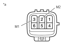
a.

Disconnect the E1 differential lock shift actuator connector.


C341715E02
1.75,0.708 2.24,0.323 true 0.865,1.042 1.323,0.813 true 0.125,0.094 0.521,0.323 0.396,0.229 10 false *a 2.292,0.198 2.594,0.385 0.302,0.188 10 false M2 0.604,0.99 0.885,1.177 0.281,0.188 10 false M1

b.

Measure the resistance according to the value(s) in the table below.

Standard Resistance:
Tester Connection Condition Specified Condition
3 (M1) - 2 (M2) Always 100 Ω or less


Text in Illustration
*a Component without harness connected
(Differential Lock Shift Actuator)


OK

REPLACE 4 WHEEL DRIVE CONTROL ECU

NG

REPLACE DIFFERENTIAL LOCK SHIFT ACTUATOR