BRAKE CONTROL / DYNAMIC CONTROL SYSTEMS VEHICLE STABILITY CONTROL SYSTEM(for Hydraulic Brake Booster) TRC OFF Indicator Light does not Come ON
DESCRIPTION
Refer to TRC OFF Indicator Light Remains ON (See page Brake>BRAKE CONTROL / DYNAMIC CONTROL SYSTEMS>VEHICLE STABILITY CONTROL SYSTEM (for Hydraulic Brake Booster)>TRC OFF Indicator Light Remains ON)
WIRING DIAGRAM
Refer to TRC OFF Indicator Light Remains ON (See page Brake>BRAKE CONTROL / DYNAMIC CONTROL SYSTEMS>VEHICLE STABILITY CONTROL SYSTEM (for Hydraulic Brake Booster)>TRC OFF Indicator Light Remains ON)
CAUTION / NOTICE / HINT
- NOTICE:
-
When replacing the skid control ECU (master cylinder solenoid), perform calibration (See page Brake>BRAKE CONTROL / DYNAMIC CONTROL SYSTEMS>VEHICLE STABILITY CONTROL SYSTEM (for Hydraulic Brake Booster)>CALIBRATION).
PROCEDURE
Turn the ignition switch off.
Connect the GTS to the DLC3.
Turn the ignition switch to ON.
Turn the GTS on.
Select CAN Bus Check from the System Selection Menu screen and follow the prompts on the screen to inspect the CAN bus.
w/ Central Gateway ECU: See pagePower Source / Network>NETWORKING>CAN COMMUNICATION SYSTEM (w/ Central Gateway ECU)>DIAGNOSIS SYSTEM
w/o Central Gateway ECU: See pagePower Source / Network>NETWORKING>CAN COMMUNICATION SYSTEM (w/o Central Gateway ECU)>DIAGNOSIS SYSTEM
- OK:
CAN Bus Check indicates no malfunctions in CAN communication.
| Result | Proceed to |
|---|---|
| OK (w/ Combination Switch Assembly) | A |
| OK (w/o Combination Switch Assembly (w/ Downhill Assist Control)) | B |
| OK (w/o Combination Switch Assembly (w/o Downhill Assist Control)) | C |
| NG (w/ Central Gateway ECU) | D |
| NG (w/o Central Gateway ECU) | E |
A
B
C
D
E
OK
NG
OK
NG
OK
NG
Remove the VSC OFF switch (combination switch assembly) (See pageBrake>BRAKE CONTROL / DYNAMIC CONTROL SYSTEMS>VSC OFF SWITCH(w/ Combination Switch)>REMOVAL).
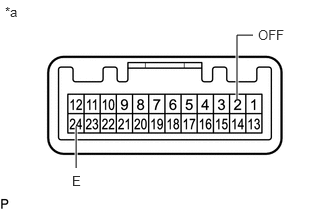
Measure the resistance according to the value(s) in the table below.
- Standard Resistance:
Tester Connection Switch Condition Specified Condition 2 (OFF) - 24 (E) Switch is not pushed 10 kΩ or higher Switch is pushed Below 1 Ω
| *a | Component without harness connected
(VSC OFF Switch (Combination Switch Assembly)) |
OK
NG
Remove the VSC OFF switch (No. 2 combination switch assembly) (See pageBrake>BRAKE CONTROL / DYNAMIC CONTROL SYSTEMS>VSC OFF SWITCH(w/o Combination Switch)>REMOVAL).
Measure the resistance according to the value(s) in the table below.
- Standard Resistance:
Tester Connection Switch Condition Specified Condition 2 (OFF) - 24 (E) Switch is not pushed 10 kΩ or higher Switch is pushed Below 1 Ω
| *a | Component without harness connected
(VSC OFF Switch (No. 2 Combination Switch Assembly)) |
OK
NG
Remove the VSC OFF switch (See pageBrake>BRAKE CONTROL / DYNAMIC CONTROL SYSTEMS>VSC OFF SWITCH(w/ Combination Switch)>REMOVAL).
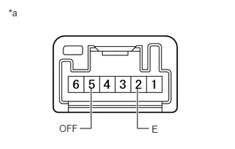
Measure the resistance according to the value(s) in the table below.
- Standard Resistance:
Tester Connection Switch Condition Specified Condition 5 (OFF) - 2 (E) Switch is not pushed 10 kΩ or higher Switch is pushed Below 1 Ω
| *a | Component without harness connected
(VSC OFF Switch) |
OK
NG
(See pageBrake>BRAKE CONTROL / DYNAMIC CONTROL SYSTEMS>VSC OFF SWITCH(w/ Combination Switch)>REMOVAL)
A
(See pageVehicle Interior>METER / GAUGE / DISPLAY>METER / GAUGE SYSTEM>HOW TO PROCEED WITH TROUBLESHOOTING)
B
C