EXTERIOR PANELS / TRIM BACK DOOR OUTSIDE GARNISH(w/o Tire Carrier) INSTALLATION
CAUTION / NOTICE / HINT
- HINT:
-
A bolt without a torque specification is shown in the standard bolt chart.
-
Click hereGeneral>SPECIFICATIONS>STANDARD BOLT>SPECIFIED TORQUE FOR STANDARD BOLTS
PROCEDURE

 76812A
1.INSTALL NO. 2 BACK DOOR OUTSIDE GARNISH
Attach the 3 claws and 2 guides to install the No. 2 back door outside garnish to back door outside garnish sub-assembly.
2.INSTALL BACK DOOR OUTSIDE GARNISH ASSEMBLY
Pass the back door electrical switch wire harness.
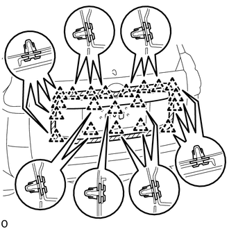
Attach the 20 clips to install the back door outside garnish assembly.
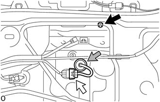

|
Nut |

|
Connector |

|
Grommet |
Attach the clamp to install the back door electrical switch wire harness.
Connect the connector.
Install the nut.
Remove the protective tape.
76827A
3.INSTALL NO. 2 BACK DOOR GARNISH RETAINER (w/o Rear View Monitor System)
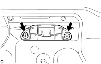
Install the No. 2 back door garnish retainer with 2 screws.
86790D
4.INSTALL REAR TELEVISION CAMERA ASSEMBLY (w/ Rear View Monitor System)
69212
5.INSTALL BACK DOOR OUTSIDE HANDLE LH
67847A
6.INSTALL BACK DOOR SERVICE HOLE COVER
64780A
7.INSTALL BACK DOOR TRIM PANEL ASSEMBLY
64798
8.INSTALL BACK DOOR LOCK COVER
09120A
9.INSTALL TOOL CASE
75202B
10.INSTALL UPPER TOOL BOX PANEL SUB-ASSEMBLY
67761A
11.INSTALL BACK DOOR TRIM COVER
67938A
12.INSTALL BACK DOOR SIDE GARNISH LH
67937B
13.INSTALL BACK DOOR SIDE GARNISH RH
67939B
14.INSTALL BACK DOOR CENTER GARNISH