Home › Vehicle Interior › METER / GAUGE / DISPLAY › METER / GAUGE SYSTEM › from 2017.08
RM27T0E _58 Vehicle Interior _053733 METER / GAUGE / DISPLAY _0261082 METER / GAUGE SYSTEM J

METER / GAUGE / DISPLAY  METER / GAUGE SYSTEM  Operating Light Control Rheostat does not Change Light Brightness  


DESCRIPTION

When the light control rheostat knob is turned right, the combination meter and vehicle interior illumination will become brighter. When the light control rheostat knob is turned left, the combination meter and vehicle illumination will dim.

WIRING DIAGRAM
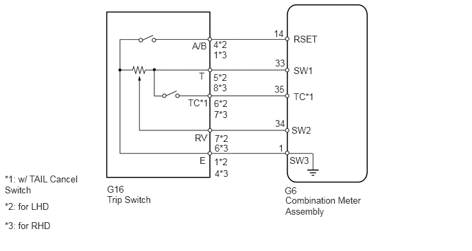
except 5L-E
E202081E07
3.24,0.594 3.833,0.979 0.594,0.385 10 false 4*2 3.24,1.094 3.875,1.281 0.635,0.188 10 false 5*2 3.25,1.49 3.906,1.667 0.656,0.177 10 false 6*2 3.26,2.021 3.76,2.198 0.5,0.177 10 false 7*2 3.25,2.375 3.781,2.542 0.531,0.167 10 false 1*2 2.917,0.615 3.563,0.948 0.646,0.333 10 false A/B 3.021,1.073 3.5,1.448 0.479,0.375 10 false T 2.854,1.479 3.469,1.833 0.615,0.354 10 false TC*1 2.958,2.01 3.563,2.406 0.604,0.396 10 false RV 3.031,2.354 3.458,2.698 0.427,0.344 10 false E 4.156,0.427 4.604,0.646 0.448,0.219 10 false 14 4.177,0.875 5.042,1.302 0.865,0.427 10 false 33 4.167,1.271 5.104,1.729 0.938,0.458 10 false 35 4.177,1.792 4.635,2.125 0.458,0.333 10 false 34 4.229,2.167 4.938,2.615 0.708,0.448 10 false 1 4.458,0.51 5.177,0.969 0.719,0.458 10 false RSET 4.458,0.99 5.156,1.427 0.698,0.438 10 false SW1 4.458,1.385 5.24,1.813 0.781,0.427 10 false TC*1 4.427,1.896 5.24,2.313 0.813,0.417 10 false SW2 4.396,2.354 5.292,2.729 0.896,0.375 10 false SW3 1.625,2.792 2.76,3.073 1.135,0.281 10 false G16 1.625,2.948 2.563,3.25 0.938,0.302 10 false Trip Switch 4.323,2.813 5.531,3.115 1.208,0.302 10 false G6 4.333,2.958 5.896,3.302 1.563,0.344 10 false Combination Meter Assembly 0.073,2.635 1.25,2.979 1.177,0.344 10 false *1: w/ TAIL Cancel Switch 0.073,3.052 1.76,3.25 1.688,0.198 10 false *2: for LHD 0.073,3.344 1.76,3.542 1.688,0.198 10 false *3: for RHD 3.24,0.75 3.698,0.948 0.458,0.198 10 false 1*3 3.24,1.25 3.698,1.448 0.458,0.198 10 false 8*3 3.25,1.656 3.708,1.854 0.458,0.198 10 false 7*3 3.26,2.167 3.719,2.365 0.458,0.198 10 false 6*3 3.26,2.552 3.719,2.75 0.458,0.198 10 false 4*3

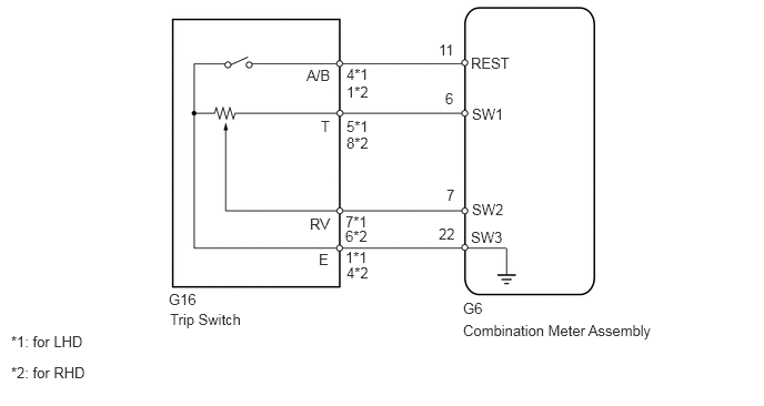
for 5L-E
E379934E01
2.875,0.625 3.198,0.813 0.323,0.188 10 false A/B 3.25,0.615 3.583,0.802 0.333,0.188 10 false 4*1 3.25,0.781 3.583,0.969 0.333,0.188 10 false 1*2 3.01,1.104 3.208,1.313 0.198,0.208 10 false T 3.25,1.104 3.583,1.292 0.333,0.188 10 false 5*1 3.25,1.26 3.583,1.448 0.333,0.188 10 false 8*2 2.906,2.021 3.219,2.229 0.313,0.208 10 false RV 2.99,2.354 3.208,2.563 0.219,0.208 10 false E 3.24,2 3.573,2.188 0.333,0.188 10 false 7*1 3.24,2.135 3.573,2.323 0.333,0.188 10 false 6*2 3.24,2.333 3.573,2.521 0.333,0.188 10 false 1*1 3.25,2.479 3.583,2.667 0.333,0.188 10 false 4*2 4.177,0.844 4.51,1.031 0.333,0.188 10 false 6 4.115,0.385 4.448,0.573 0.333,0.188 10 false 11 4.188,1.75 4.521,1.938 0.333,0.188 10 false 7 4.115,2.115 4.448,2.302 0.333,0.188 10 false 22 4.417,0.51 4.948,0.74 0.531,0.229 10 false REST 4.427,0.99 4.802,1.188 0.375,0.198 10 false SW1 4.427,1.885 4.865,2.094 0.438,0.208 10 false SW2 4.417,2.146 4.854,2.375 0.438,0.229 10 false SW3 4.344,2.813 4.677,3 0.333,0.188 10 false G6 4.344,3.021 6.313,3.292 1.969,0.271 10 false Combination Meter Assembly 1.583,2.729 1.917,2.917 0.333,0.188 10 false G16 1.594,2.917 2.635,3.198 1.042,0.281 10 false Trip Switch 0.104,3.125 1.052,3.354 0.948,0.229 10 false *1: for LHD 0.104,3.417 1.104,3.615 1,0.198 10 false *2: for RHD

PROCEDURE

1.READ VALUE USING GTS (TAIL CANCEL SW, RHEOSTAT VALUE)
a.

Using the GTS, read the Data List (See page Vehicle Interior>METER / GAUGE / DISPLAY>METER / GAUGE SYSTEM>DATA LIST / ACTIVE TEST).

Combination Meter
Tester Display Measurement Item/Range Normal Condition Diagnostic Note
Tail Cancel SW* Tail cancel switch/OFF or ON OFF: Tail cancel switch off -
ON: Tail cancel switch on
Rheostat value Light control rheostat switch input/Min.: 0, Max.: 100 Light control rheostat switch is fully turned right (0) → fully turned left (100) Unit: %

*: w/ TAIL Cancel Switch


OK:

Light brightness can be changed within specified range by manual operation.


OK

REPLACE COMBINATION METER ASSEMBLY

NG

2.CHECK HARNESS AND CONNECTOR (COMBINATION METER ASSEMBLY - TRIP SWITCH [LIGHT CONTROL RHEOSTAT])
a.

Disconnect the G304*1, G6*2 combination meter assembly connector.

*1: except 5L-E


b.

Disconnect the G16 trip switch (light control rheostat) connector.


c.

Measure the resistance according to the value(s) in the table below.

Standard Resistance (except 5L-E):
for LHD
Tester Connection Condition Specified Condition
G304-35 (TC) - G16-6 (TC)* Always Below 1 Ω
G304-33 (SW1) - G16-5 (T) Always Below 1 Ω
G304-34 (SW2) - G16-7 (RV) Always Below 1 Ω
G304-1 (SW3) - G16-1 (E) Always Below 1 Ω

for RHD
Tester Connection Condition Specified Condition
G304-35 (TC) - G16-7 (TC)* Always Below 1 Ω
G304-33 (SW1) - G16-8 (T) Always Below 1 Ω
G304-34 (SW2) - G16-6 (RV) Always Below 1 Ω
G304-1 (SW3) - G16-4 (E) Always Below 1 Ω


*: w/ TAIL Cancel Switch


Standard Resistance (for 5L-E):
for LHD
Tester Connection Condition Specified Condition
G6-6 (SW1) - G16-5 (T) Always Below 1 Ω
G6-7 (SW2) - G16-7 (RV) Always Below 1 Ω
G6-22 (SW3) - G16-1 (E) Always Below 1 Ω

for RHD
Tester Connection Condition Specified Condition
G6-6 (SW1) - G16-8 (T) Always Below 1 Ω
G6-7 (SW2) - G16-6 (RV) Always Below 1 Ω
G6-22 (SW3) - G16-4 (E) Always Below 1 Ω


OK

3.CHECK COMBINATION METER ASSEMBLY

NG

REPAIR OR REPLACE HARNESS OR CONNECTOR

3.CHECK COMBINATION METER ASSEMBLY
a.

Replace the combination meter assembly with a new or normally operating one. Perform an operation inspection.

OK:

Combination meter assembly operates normally.


OK

END (COMBINATION METER ASSEMBLY IS DEFECTIVE)

NG

REPLACE TRIP SWITCH (LIGHT CONTROL RHEOSTAT)