Home › Engine / Hybrid System › 1GR-FE (ENGINE CONTROL) › SFI SYSTEM › from 2017.08
RM27T0E _51 Engine / Hybrid System _053657 1GR-FE ENGINE CONTROL _0260436 SFI SYSTEM C

1GR-FE ENGINE CONTROL  SFI SYSTEM  P0412  Secondary Air Injection System Switching Valve "A" Circuit  


DESCRIPTION

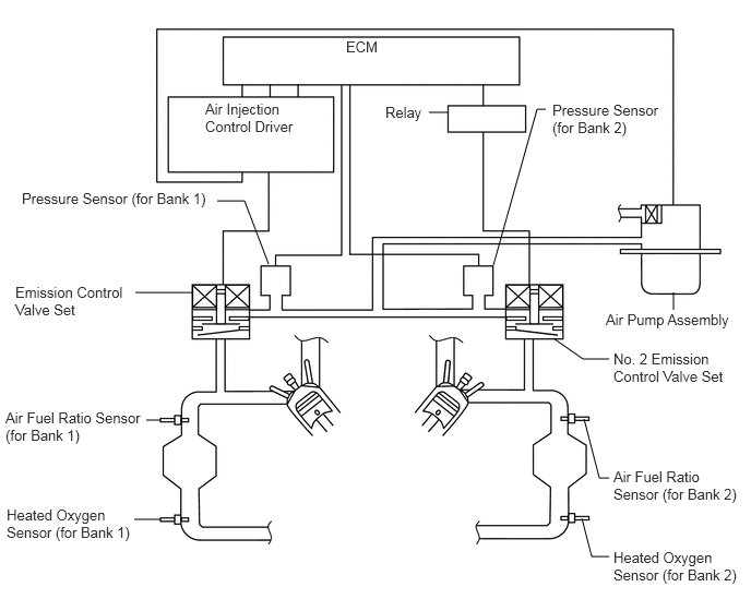
The secondary air injection system injects air into the exhaust port of the cylinder head using an electric air pump, starting when the engine is started cold and operating until the catalyst warms up, in order to promote combustion of unburned fuel and decrease the amount of hydrocarbons (HC) and carbon monoxide (CO) in the exhaust gas.
A217752E12
4.094,1.073 4.271,1.073 false 5.208,1.042 5.125,1.042 5.125,1.042 4.708,2.531 false 2.073,1.917 2.333,1.917 2.333,1.917 2.563,2.521 false 1.292,2.792 1.833,2.792 false 1.531,4.01 1.396,4.01 false 1.531,4.958 1.281,4.958 false 5.813,3.427 5.563,3.427 5.563,3.427 5.281,3.229 false 5.813,4.563 5.719,4.563 5.719,4.563 5.573,4 false 5.813,5.313 5.646,5.313 5.646,5.313 5.552,4.948 false 6.427,2.958 6.427,2.792 false 3.302,0.365 3.771,0.542 0.469,0.177 10 false ECM 1.958,0.958 2.865,1.313 0.906,0.354 10 false Air Injection Control Driver 0.208,1.813 2.104,2.031 1.896,0.219 10 false Pressure Sensor (for Bank 1) 0.146,2.708 1.281,3.094 1.135,0.385 10 false Emission Control Valve Set 5.781,2.969 7.063,3.167 1.281,0.198 10 false Air Pump Assembly 0.063,4.833 1.344,5.208 1.281,0.375 10 false Heated Oxygen Sensor (for Bank 1) 0.052,3.906 1.406,4.26 1.354,0.354 10 false Air Fuel Ratio Sensor (for Bank 1) 3.677,0.99 4.125,1.177 0.448,0.188 10 false Relay 5.271,0.969 6.385,1.302 1.115,0.333 10 false Pressure Sensor (for Bank 2) 5.854,3.344 7.042,3.719 1.188,0.375 10 false No. 2 Emission Control Valve Set 5.854,5.24 7.104,5.583 1.25,0.344 10 false Heated Oxygen Sensor (for Bank 2) 5.854,4.469 7.125,4.813 1.271,0.344 10 false Air Fuel Ratio Sensor (for Bank 2)

DTC No. DTC Detection Condition Trouble Area
P0412

All conditions are met for 3 seconds or more while idling immediately after the engine is started (1 trip detection logic):

(a)

Secondary Air Injection system is not operating (the air pump assembly and emission control valve set are off).

(b)

Diagnostic signal from the Air Injection Control Driver 40%.

(c)

Battery voltage is 8 V or higher


·

Open in emission control valve set drive circuit (for bank 1)

·

Air injection control driver

·

Emission control valve set


All conditions are met for 3 seconds or more while idling immediately after the engine is started (1 trip detection logic):

(a)

Secondary Air Injection system is operating (the air pump assembly and Emission Control Valve Set are on).

(b)

Diagnostic signal from the Air Injection Control Driver 40%.

(c)

Battery voltage is 8 V or higher.


·

Short between emission control valve set drive circuit and body ground (for bank 1)

·

Air injection control driver

·

Emission control valve set


MONITOR DESCRIPTION

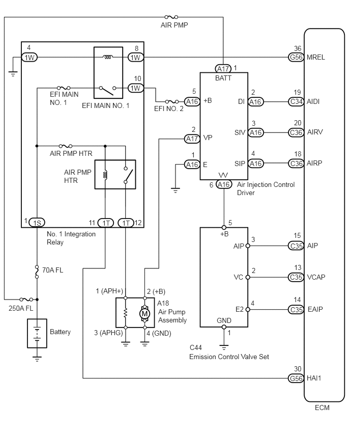
This DTC indicates an open or short circuit in the circuit containing the emission control valve set of the secondary air injection system. The air injection control driver performs diagnosis of the air pump assembly, air switching valve (bank 1) and itself and sends the results of this diagnosis to the ECM as a duty signal. When the ECM receives a signal indicating a malfunction in the air pump assembly, emission control valve set or air injection control driver, it illuminates the MIL and stores a DTC.

WIRING DIAGRAM
A412531E01
6.281,1.083 6.896,1.281 0.615,0.198 10 false MREL 5.938,1.083 6.396,1.281 0.458,0.198 10 false G56 6.021,0.906 6.333,1.104 0.313,0.198 10 false 36 2.667,1.094 2.979,1.292 0.313,0.198 10 false 1W 2.76,0.906 2.917,1.104 0.156,0.198 10 false 8 1.677,2.073 2.771,2.292 1.094,0.219 10 false EFI MAIN NO. 1 2.667,1.719 2.979,1.917 0.313,0.198 10 false 1W 2.74,1.521 3.052,1.719 0.313,0.198 10 false 10 1.021,1.844 1.656,2.198 0.635,0.354 10 false EFI MAIN NO. 1 0.5,1.094 0.813,1.292 0.313,0.198 10 false 1W 0.552,0.885 0.708,1.083 0.156,0.198 10 false 4 0.677,4.479 0.99,4.677 0.313,0.198 10 false 1S 0.49,4.427 0.646,4.625 0.156,0.198 10 false 1 6.281,1.99 6.896,2.188 0.615,0.198 10 false AIDI 5.948,1.99 6.406,2.188 0.458,0.198 10 false C34 5.948,3.26 6.406,3.458 0.458,0.198 10 false C36 5.938,2.625 6.396,2.823 0.458,0.198 10 false C36 5.104,2 5.563,2.198 0.458,0.198 10 false A16 5.115,2.625 5.573,2.823 0.458,0.198 10 false A16 5.115,3.26 5.573,3.458 0.458,0.198 10 false A16 4.458,3.688 4.917,3.885 0.458,0.198 10 false A16 3.813,3.281 4.271,3.479 0.458,0.198 10 false A16 4.448,1.323 4.906,1.521 0.458,0.198 10 false A17 3.813,2.75 4.271,2.948 0.458,0.198 10 false A17 3.813,1.99 4.271,2.188 0.458,0.198 10 false A16 4.406,1.51 5.021,1.708 0.615,0.198 10 false BATT 4.875,1.99 5.188,2.188 0.313,0.198 10 false DI 6.01,1.802 6.323,2 0.313,0.198 10 false 19 5.146,1.802 5.302,2 0.156,0.198 10 false 2 5.156,2.438 5.313,2.635 0.156,0.198 10 false 3 6.021,2.427 6.333,2.625 0.313,0.198 10 false 20 6.021,3.063 6.333,3.26 0.313,0.198 10 false 18 5.146,3.052 5.302,3.25 0.156,0.198 10 false 4 4.479,3.5 4.792,3.698 0.313,0.198 10 false VV 4.854,3.688 6.104,4.052 1.25,0.365 10 false Air Injection Control Driver 4.292,3.698 4.448,3.896 0.156,0.198 10 false 6 4.802,2.625 5.26,2.823 0.458,0.198 10 false SIV 6.292,2.615 6.906,2.813 0.615,0.198 10 false AIRV 6.281,3.25 6.896,3.448 0.615,0.198 10 false AIRP 4.802,3.26 5.26,3.458 0.458,0.198 10 false SIP 4.167,1.969 4.479,2.167 0.313,0.198 10 false +B 4.167,2.729 4.781,2.927 0.615,0.198 10 false VP 4.156,3.281 4.313,3.479 0.156,0.198 10 false E 4.781,1.302 4.938,1.5 0.156,0.198 10 false 1 3.938,1.781 4.094,1.979 0.156,0.198 10 false 5 3.927,2.563 4.083,2.76 0.156,0.198 10 false 2 3.917,3.083 4.073,3.281 0.156,0.198 10 false 1 3.292,0.427 4.365,0.625 1.073,0.198 10 false AIR PMP 3.01,5.875 3.927,6.073 0.917,0.198 10 false 2 (+B) 3,6.729 4.073,6.927 1.073,0.198 10 false 4 (GND) 1.958,5.865 3.188,6.063 1.229,0.198 10 false 1 (APH+) 1.927,6.719 3.156,6.917 1.229,0.198 10 false 3 (APHG) 3.219,6.115 3.677,6.313 0.458,0.198 10 false A18 3.24,6.292 3.896,6.667 0.656,0.375 10 false Air Pump Assembly 4.677,4.469 4.833,4.667 0.156,0.198 10 false 5 4.51,4.698 4.823,4.896 0.313,0.198 10 false +B 4.781,4.948 5.24,5.146 0.458,0.198 10 false AIP 4.792,5.583 5.104,5.781 0.313,0.198 10 false VC 5.146,4.813 5.302,5.01 0.156,0.198 10 false 3 5.156,5.448 5.313,5.646 0.156,0.198 10 false 2 4.823,6.24 5.135,6.438 0.313,0.198 10 false E2 5.135,6.115 5.448,6.313 0.313,0.198 10 false 4 4.438,6.469 4.896,6.667 0.458,0.198 10 false GND 4.656,6.719 4.813,6.917 0.156,0.198 10 false 1 3.885,7.021 4.344,7.219 0.458,0.198 10 false C44 3.875,7.208 5.656,7.427 1.781,0.219 10 false Emission Control Valve Set 5.948,4.948 6.406,5.146 0.458,0.198 10 false C35 5.938,5.583 6.396,5.781 0.458,0.198 10 false C35 5.948,6.25 6.406,6.448 0.458,0.198 10 false C35 6.01,4.729 6.323,4.927 0.313,0.198 10 false 15 6.021,5.385 6.333,5.583 0.313,0.198 10 false 13 6.01,6.042 6.323,6.24 0.313,0.198 10 false 14 6.292,4.938 6.75,5.135 0.458,0.198 10 false AIP 6.292,5.583 6.906,5.781 0.615,0.198 10 false VCAP 6.302,6.24 6.917,6.438 0.615,0.198 10 false EAIP 2.5,4.479 2.813,4.677 0.313,0.198 10 false 1T 2.75,4.469 3.063,4.667 0.313,0.198 10 false 12 2.094,4.479 2.406,4.677 0.313,0.198 10 false 1T 1.813,4.469 2.125,4.667 0.313,0.198 10 false 11 1.313,3.438 1.927,3.833 0.615,0.396 10 false AIR PMP HTR 1.021,3.052 2.708,3.25 1.688,0.198 10 false AIR PMP HTR 6.281,7.646 6.896,7.844 0.615,0.198 10 false HAI1 5.938,7.656 6.396,7.854 0.458,0.198 10 false G56 6.021,7.458 6.333,7.656 0.313,0.198 10 false 30 0.865,5.438 1.458,5.646 0.594,0.208 10 false 70A FL 0.177,6.219 0.771,6.396 0.594,0.177 10 false 250A FL 0.958,4.698 2,5.104 1.042,0.406 10 false No. 1 Integration Relay 3.156,2.135 4.531,2.333 1.375,0.198 10 false EFI NO. 2 6.448,8.25 6.906,8.448 0.458,0.198 10 false ECM 1.021,6.698 2.094,6.896 1.073,0.198 10 false Battery

CAUTION / NOTICE / HINT

NOTICE:

Inspect the fuses of circuits related to this system before performing the following inspection procedure.


HINT:
·

By using the GTS to perform the Secondary Air Injection Check operation in the system check, the air-fuel ratio and the pressure in the secondary air injection system passage can be checked while the secondary air injection system is operating. This helps technicians to troubleshoot the system when it malfunctions.

·

Read freeze frame data using the GTS. Freeze frame data records the engine condition when malfunctions are detected. When troubleshooting, freeze frame data can help determine if the vehicle was moving or stationary, if the engine was warmed up or not, if the air-fuel ratio was lean or rich, and other data from the time the malfunction occurred.


PROCEDURE
1.INSPECT EMISSION CONTROL VALVE SET
a.
A160404E11
0.73,2.866 0.969,3.035 0.239,0.170 10 +B 0.08,0.012 0.260,0.182 0.180,0.170 10 *a 2.392,2.866 2.763,3.035 0.371,0.170 10 GND 1.116,2.074 0.837,2.858 false 2.586,2.866 2.158,2.071 false

Disconnect the emission control valve set connector.


b.

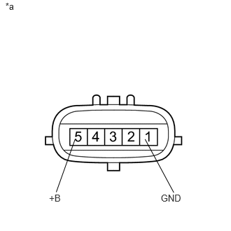
Measure the resistance according to the value(s) in the table below.

Standard Resistance:
Tester Connection Condition Specified Condition
5 (+B) - 1 (GND) 20°C (68°F) 4.5 to 5.5 Ω


Text in Illustration
*a Component without harness connected
(Emission Control Valve Set)


c.

Reconnect the emission control valve set connector.


OK

2.CHECK HARNESS AND CONNECTOR (EMISSION CONTROL VALVE SET - BODY GROUND)

NG

2.CHECK HARNESS AND CONNECTOR (EMISSION CONTROL VALVE SET - BODY GROUND)
a.

Disconnect the emission control valve set connector.


b.

Measure the resistance according to the value(s) in the table below.

Standard Resistance:
Tester Connection Condition Specified Condition
C44-1 (GND) - Body ground Always Below 1 Ω


c.

Reconnect the emission control valve set connector.


OK

3.CHECK HARNESS AND CONNECTOR (EMISSION CONTROL VALVE SET - AIR INJECTION CONTROL DRIVER)

NG

REPAIR OR REPLACE HARNESS OR CONNECTOR

3.CHECK HARNESS AND CONNECTOR (EMISSION CONTROL VALVE SET - AIR INJECTION CONTROL DRIVER)
a.

Disconnect the emission control valve set connector.


b.

Disconnect the air injection control driver connector.


c.

Measure the resistance according to the value(s) in the table below.

Standard Resistance (Check for Open):
Tester Connection Condition Specified Condition
C44-5 (+B) - A16-6 (VV) Always Below 1 Ω


Standard Resistance (Check for Short):
Tester Connection Condition Specified Condition
C44-5 (+B) or A16-6 (VV) - Body ground Always 10 kΩ or higher


d.

Reconnect the emission control valve set connector.


e.

Reconnect the air injection control driver connector.


OK

NG

REPAIR OR REPLACE HARNESS OR CONNECTOR