THEFT DETERRENT / KEYLESS ENTRY ENTRY AND START SYSTEM(for Start Function) Power Source Mode does not Change to ON (IG)
DESCRIPTION
If the engine switch is pressed with the electrical key transmitter sub-assembly in the cabin, the certification ECU (smart key ECU assembly) receives a signal and changes the power source mode.
| Problem Symptom | Data List and Active Test |
|---|---|
| Power source mode does not change to on (IG) but does change to on (ACC) | Power Source Control
·
Power Supply Condition ·
IG Relay Monitor (Inside) ·
IG Relay Monitor (Outside) |
WIRING DIAGRAM
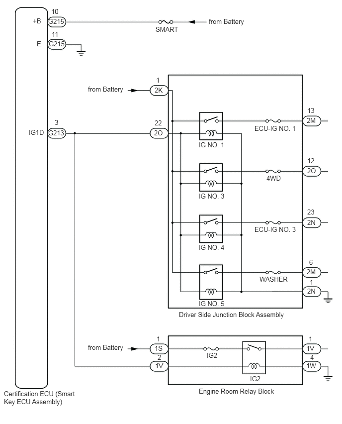
CAUTION / NOTICE / HINT
- NOTICE:
- ·
When using the GTS with the engine switch off, connect the GTS to the DLC3 and turn a courtesy light switch on and off at intervals of 1.5 seconds or less until communication between the GTS and the vehicle begins. Then select Model Code "KEY REGIST" under manual mode and enter the following menus: Body Electrical / Entry&Start(CAN). While using the GTS, periodically turn a courtesy light switch on and off at intervals of 1.5 seconds or less to maintain communication between the GTS and the vehicle.
·Make sure that no DTCs are output. If any DTCs are output, proceed to Diagnostic Trouble Code Chart.
·If the entry and start system (for Start Function) has been canceled, enable the system before performing troubleshooting.
·Inspect the fuses of circuits related to this system before performing the following procedure.
·Before replacing the certification ECU (smart key ECU assembly), refer to the Service Bulletin.
·After completing repairs, confirm that the problem does not recur.
·After repair, confirm that no DTCs are output by performing "DTC Output Confirmation Operation".
PROCEDURE
Connect the GTS to the DLC3.
Turn the engine switch on (IG).
Turn the GTS on.
Enter the following menus: Body Electrical / Entry&Start, Power Source Control / Trouble Codes.
- Result:
Result Proceed to DTCs are not output A Entry and start system (for Start Function) DTCs are output B
A
B
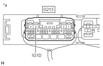
| *a | Component with harness connected
(Certification ECU (Smart Key ECU Assembly)) |
Measure the voltage according to the value(s) in the table below.
- Standard Voltage:
Tester Connection Switch Condition Specified Condition G213-3 (IG1D) - Body ground Engine switch on (ACC) → Engine switch on (IG) 1 V or less → 8.5 V or higher
- Result:
Proceed to OK NG
OK
NG
Disconnect the G213 certification ECU (smart key ECU assembly) connector.
Disconnect the 2K, 2O and 2N driver side junction block assembly connectors.
Measure the resistance according to the value(s) in the table below.
- Standard Resistance:
Tester Connection Condition Specified Condition G213-3 (IG1D) - 2O-22 Always Below 1 Ω 2N-1 - Body ground Always Below 1 Ω G213-3 (IG1D) or 2O-22 - Body ground Always 10 kΩ or higher
Measure the voltage according to the value(s) in the table below.
- Standard Voltage:
Tester Connection Condition Specified Condition 2K-1 - Body ground Always 11 to 14 V
Reconnect the G213 certification ECU (smart key ECU assembly) connector.
- Result:
Proceed to OK NG
OK
NG
Remove the driver side junction block assembly.
Click herePower Source / Network>POWER DISTRIBUTION>MAIN BODY ECU>REMOVAL
Reconnect the all driver side junction block assembly connectors.
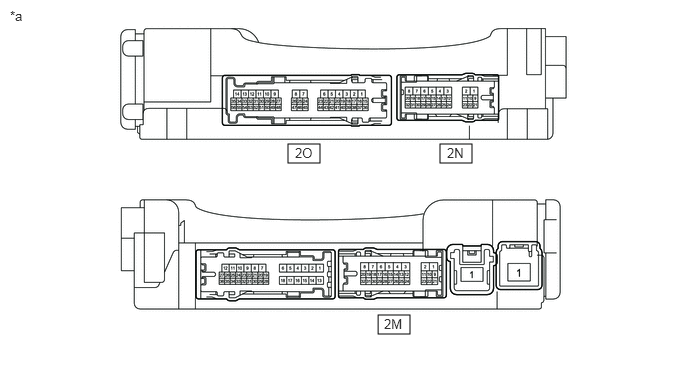
| *a | Component with harness connected
(Driver Side Junction Block Assembly) |
- | - |
Measure the voltage according to the value(s) in the table below.
- Standard Voltage:
Tester Connection Switch Condition Specified Condition 2M-13 - Body ground Engine switch on (IG) 9 to 14 V 2O-12 - Body ground Engine switch on (IG) 9 to 14 V 2N-23 - Body ground Engine switch on (IG) 9 to 14 V 2M-6 - Body ground Engine switch on (IG) 9 to 14 V
- Result:
Proceed to OK NG
OK
NG
Disconnect the G213 certification ECU (smart Key ECU assembly) connector.
Disconnect the 1V, 1W and 1S engine room relay block connectors.
Disconnect the 2O driver side junction block assembly connector.
Measure the resistance according to the value(s) in the table below.
- Standard Resistance:
Tester Connection Condition Specified Condition G213-3 (IG1D) - 1V-2 Always Below 1 Ω 1W-4 - Body ground Always Below 1 Ω G213-3 (IG1D) or 1V-2 - Body ground Always 10 kΩ or higher
Measure the voltage according to the value(s) in the table below.
- Standard Voltage:
Tester Connection Condition Specified Condition 1S-1 - Body ground Always 11 to 14 V
Reconnect the G213 certification ECU (smart Key ECU assembly) connector.
- Result:
Proceed to OK NG
OK
NG
Reconnect the all engine room relay block connectors.
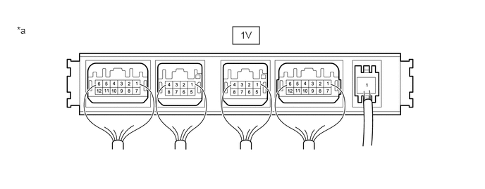
| *a | Component with harness connected
(Engine Room Relay Block) |
- | - |
Measure the voltage according to the value(s) in the table below.
- Standard Voltage:
Tester Connection Switch Condition Specified Condition 1V-1 - Body ground Engine switch on (IG) 9 to 14 V
- Result:
Proceed to OK NG
OK
Click hereGeneral>INTRODUCTION>HOW TO TROUBLESHOOT ECU CONTROLLED SYSTEMS>HOW TO PROCEED WITH TROUBLESHOOTING
NG