Home › Engine / Hybrid System › 1GD-FTV (ENGINE CONTROL) › MANIFOLD ABSOLUTE PRESSURE SENSOR › 2018.06–2021.06
RM27T0E _51 Engine / Hybrid System _053660 1GD-FTV ENGINE CONTROL _0260469 MANIFOLD ABSOLUTE PRESSURE SENSOR A

1GD-FTV ENGINE CONTROL  MANIFOLD ABSOLUTE PRESSURE SENSOR  INSTALLATION  


PROCEDURE

Hide 89421C 1.INSTALL DIESEL TURBO PRESSURE SENSOR

a.

w/o Clip:

i.

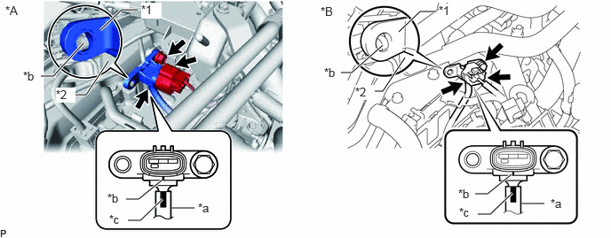
Connect the vacuum hose to the diesel turbo pressure sensor.
A424428C02
6.115,2.396 6.385,2.396 true 0.865,1.115 1.01,1.115 1.01,1.115 1.271,0.719 true 1.177,0.354 1.427,0.115 1.427,0.115 1.615,0.115 true 0.479,0.896 0.625,0.896 0.625,0.896 0.979,0.51 true 4.344,1.073 4.49,1.073 4.49,1.073 4.75,0.677 true 3.979,0.854 4.125,0.854 4.125,0.854 4.49,0.531 true 4.677,0.375 4.927,0.135 4.927,0.135 5.115,0.135 true 2.01,2.448 2.281,2.448 true 1.5,2.594 1.646,2.594 1.646,2.594 1.906,2.344 true 1.479,2.344 1.625,2.344 1.625,2.344 1.906,2.115 true 5.604,2.521 5.75,2.521 5.75,2.521 6.01,2.271 true 5.573,2.281 5.719,2.281 5.719,2.281 6,2.052 true 0.063,0.042 0.375,0.198 0.313,0.156 10 false *A 3.76,0.052 4.073,0.208 0.313,0.156 10 false *B 1.656,0.031 1.896,0.219 0.24,0.188 10 true *1 0.656,1.031 0.885,1.208 0.229,0.177 10 true *2 6.458,2.313 6.698,2.49 0.24,0.177 10 false *a 1.26,2.25 1.458,2.427 0.198,0.177 10 true *b 1.281,2.5 1.594,2.656 0.313,0.156 10 false *c 5.146,0.042 5.385,0.229 0.24,0.188 10 true *1 4.167,1 4.396,1.177 0.229,0.177 10 true *2 2.323,2.365 2.563,2.542 0.24,0.177 10 false *a 0.271,0.813 0.469,0.99 0.198,0.177 10 true *b 3.802,0.771 4,0.948 0.198,0.177 10 true *b 5.375,2.198 5.573,2.375 0.198,0.177 10 true *b 5.385,2.417 5.698,2.573 0.313,0.156 10 false *c
*A w/o Urea SCR System *B w/ Urea SCR System
*1 Diesel Turbo Pressure Sensor *2 No. 3 Water By-pass Pipe Sub-assembly
*a Vacuum Hose *b Protrusion
*c Paint Mark - -


NOTICE:

Connect the vacuum hose so that the paint mark on the vacuum hose is aligned with the protrusions of the diesel turbo pressure sensor as shown in the illustration.


ii.

Install the diesel turbo pressure sensor with the bolt.

Torque:
10 N*m (102 kgf*cm, 7 ft.*lbf)

NOTICE:

Make sure the protrusion of the No. 3 water bypass pipe sub-assembly is inserted into the hole of the diesel turbo pressure sensor.


iii.

Connect the diesel turbo pressure sensor connector.


b.

w/ Clip:

i.

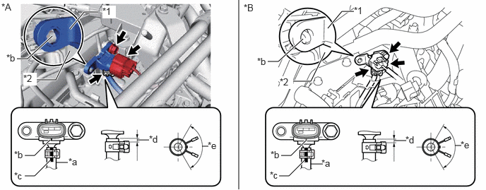
Connect the vacuum hose to the diesel turbo pressure sensor, and slide the clip to secure the vacuum hose.
A489174C01
3.521,2.792 3.521,0 false 1.448,0.177 1.24,0.177 1.24,0.177 1.031,0.427 true 1.031,0.75 0.823,1.177 0.823,1.177 0.531,1.177 true 0.771,0.531 0.406,0.865 0.406,0.865 0.25,0.865 true 0.74,2.063 0.51,2.292 0.51,2.292 0.365,2.292 true 0.74,2.365 0.51,2.594 0.51,2.594 0.365,2.594 true 0.823,2.396 1,2.396 false 2.021,2.063 2.198,2.063 false 2.979,2.156 3.073,2.156 false 5.25,0.167 5.042,0.167 5.042,0.167 4.833,0.417 true 4.469,0.573 4.104,0.906 4.104,0.906 3.948,0.906 true 4.792,0.771 4.583,1.198 4.583,1.198 4.292,1.198 true 4.521,2.063 4.292,2.292 4.292,2.292 4.146,2.292 true 4.49,2.365 4.26,2.594 4.26,2.594 4.115,2.594 true 4.583,2.417 4.76,2.417 false 5.813,2.073 5.99,2.073 false 6.708,2.146 6.802,2.146 false 0.021,0.021 0.333,0.219 0.313,0.198 10 false *A 3.594,0.031 3.906,0.229 0.313,0.198 10 false *B 1.51,0.083 1.708,0.271 0.198,0.188 10 true *1 0.344,1.073 0.542,1.26 0.198,0.188 10 true *2 0.094,0.771 0.292,0.958 0.198,0.188 10 false *b 0.208,2.198 0.406,2.385 0.198,0.188 10 false *b 0.208,2.51 0.406,2.698 0.198,0.188 10 false *c 1.01,2.302 1.208,2.49 0.198,0.188 10 false *a 2.198,1.969 2.396,2.156 0.198,0.188 10 false *d 3.063,2.063 3.26,2.25 0.198,0.188 10 false *e 5.219,0.073 5.417,0.26 0.198,0.188 10 true *1 3.792,0.823 3.99,1.01 0.198,0.188 10 false *b 4.125,1.125 4.323,1.313 0.198,0.188 10 true *2 3.99,2.198 4.188,2.385 0.198,0.188 10 false *b 3.979,2.5 4.177,2.688 0.198,0.188 10 false *c 4.74,2.323 4.938,2.51 0.198,0.188 10 false *a 5.979,1.979 6.177,2.167 0.198,0.188 10 false *d 6.792,2.052 6.99,2.24 0.198,0.188 10 false *e
*A w/o Urea SCR System *B w/ Urea SCR System
*1 Diesel Turbo Pressure Sensor *2 No. 3 Water By-pass Pipe Sub-assembly
*a Vacuum Hose *b Protrusion
*c Paint Mark *d 0 to 4 mm (0 to 0.157 in.)
*e 120° - -


NOTICE:
·

Connect the vacuum hose so that the paint mark on the vacuum hose is aligned with the protrusions of the diesel turbo pressure sensor as shown in the illustration.

·

Align the vacuum hose and the clip at the locations shown in the illustration and install them.


ii.

Install the diesel turbo pressure sensor with the bolt.

Torque:
10 N*m (102 kgf*cm, 7 ft.*lbf)

NOTICE:

Make sure the protrusion of the No. 3 water bypass pipe sub-assembly is inserted into the hole of the diesel turbo pressure sensor.


iii.

Connect the diesel turbo pressure sensor connector.


Hide 12601B 2.INSTALL NO. 1 ENGINE COVER SUB-ASSEMBLY