1GD-FTV ENGINE CONTROL DIESEL THROTTLE BODY INSTALLATION
PROCEDURE

 26100G
1.INSTALL DIESEL THROTTLE BODY ASSEMBLY
w/o Urea SCR System:
Connect the connector to install the emission control valve wire to the diesel throttle body assembly.
Connect the No. 11 water by-pass hose and No. 14 water by-pass hose to the diesel throttle body assembly, and slide the 2 clips to secure the hose. (for Cold Area Specification Vehicles)
Attach the clamp, and then connect the emission control valve wire to the wire harness clamp bracket.
Connect the connector.
Install a new gasket and the diesel throttle body assembly with the 2 bolts and 2 nuts.
- HINT:
-
If installing the diesel throttle body assembly is difficult, using an E6 "TORX" socket wrench to remove the 2 stud bolts, install the diesel throttle body assembly.
- Torque:
- Bolt and Nut : 10 N*m (102 kgf*cm, 7 ft.*lbf)
- Stud Bolt : 5.0 N*m (51 kgf*cm, 44 in.*lbf)
w/ Urea SCR System:
Connect the connector to install the emission control valve wire to the diesel throttle body assembly.
Connect the No. 11 water by-pass hose and No. 14 water by-pass hose to the diesel throttle body assembly, and slide the 2 clips to secure the hose.
Attach the clamp, and then connect the emission control valve wire to the wire harness clamp bracket.
Connect the connector.
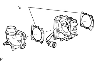
| *a | Claw |
Install 2 new gaskets and the diesel throttle body assembly and air intake connector with the 4 bolts.
- Torque:
- 10 N*m (102 kgf*cm, 7 ft.*lbf)
- NOTICE:
-
The claws of the 2 gaskets must face the diesel throttle body assembly side shown in the illustration.
Install the wire harness clamp bracket to the air intake connector with the bolt.
- Torque:
- 8.0 N*m (82 kgf*cm, 71 in.*lbf)
Connect the connector and clamp to the intake air temperature sensor and wire harness clamp bracket.
77246C
2.INSTALL FUEL MAIN TUBE SUPPORT (w/ Urea SCR System)
Install the bolt and fuel main tube support to the diesel throttle body assembly.
- Torque:
- 8.0 N*m (82 kgf*cm, 71 in.*lbf)
Attach the 2 clamps and connect the No. 1 fuel hose and breather hose to the fuel main tube support.
17030
3.INSTALL AIR HOSE ASSEMBLY (w/ Urea SCR System)
17360A
4.INSTALL AIR TUBE ASSEMBLY (w/o Urea SCR System)
Install the air tube assembly to the diesel throttle body assembly and tighten the hose clamp.
- Torque:
- 6.5 N*m (66 kgf*cm, 58 in.*lbf)
Connect the connector to the intake air temperature sensor.
Temporarily install the air tube support bracket with the 3 bolts.
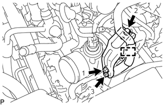
Tighten the 3 bolts in the order shown in the illustration.
- Torque:
- 6.0 N*m (61 kgf*cm, 53 in.*lbf)
Attach the clamp and connect the No. 1 fuel hose to the air tube support bracket.
17342F
5.INSTALL NO. 2 INTERCOOLER AIR HOSE (w/o Urea SCR System)
Install the No. 2 intercooler air hose and tighten the 2 hose clamps.
- Torque:
- 5.0 N*m (51 kgf*cm, 44 in.*lbf)
Connect the oil return hose and slide the 2 clips to secure the hose.
6.ADD ENGINE COOLANT
7.INSPECT FOR ENGINE COOLANT LEAK
12601B
8.INSTALL NO. 1 ENGINE COVER SUB-ASSEMBLY
While pushing the No. 1 engine cover sub-assembly towards the rear, attach the 2 rear pins.
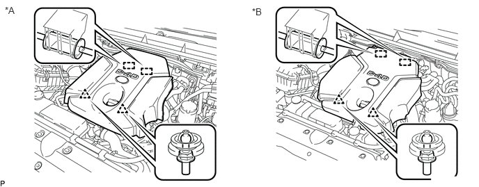
| *A | w/o Urea SCR System | *B | w/ Urea SCR System |
Attach the 2 front clips to install the No. 1 engine cover sub-assembly.
9. PERFORM INITIALIZATION
w/o Urea SCR System:
Click hereEngine / Hybrid System>1GD-FTV (ENGINE CONTROL)>ECD SYSTEM>INITIALIZATION
w/ Urea SCR System:
Click hereEngine / Hybrid System>1GD-FTV (ENGINE CONTROL)>ECD SYSTEM (w/ Urea SCR System)>INITIALIZATION