EXTERIOR PANELS / TRIM FRONT BUMPER REASSEMBLY
PROCEDURE

 1.INSTALL FRONT BUMPER GUARD ASSEMBLY (w/ Front Bumper Guard)
When installing the front bumper guard assembly to a new front bumper cover:
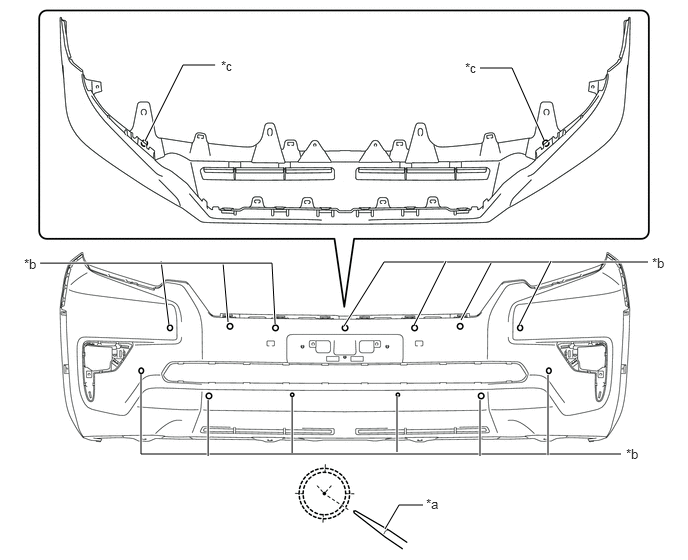
| *a | Center Punch | *b | Mark-off Line A |
| *c | Mark-off Line B | - | - |
Using a center punch, mark the centers of the mark-off line.
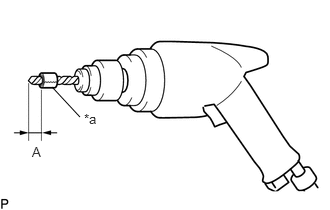
| *a | Tape |
Tape the 3.0 mm (0.12 in.) drill bit, 7.0 mm (0.28 in.) drill bit and 16 mm (0.63 in.) drill bit 10 mm (0.394 in.) from the tip as shown in the illustration.
- Standard Measurement:
Area Measurement A 10 mm (0.394 in.)
- NOTICE:
-
Tape the drill bit to prevent the drill bit from going too deep.
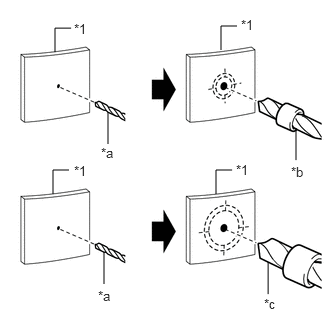
| *1 | Front Bumper Cover |
| *a | 3.0 mm (0.12 in.) Drill Bit |
| *b | 7.0 mm (0.28 in.) Drill Bit |
| *c | 16 mm (0.63 in.) Drill Bit |
Insert the 3.0 mm (0.12 in.) drill bit into a drill.
Drill a 3.0 mm (0.12 in.) pilot holes into the mark-off line.
Insert the 7.0 mm (0.28 in.) drill bit into a drill.
Drill a 7.0 mm (0.28 in.) holes into the mark-off line B.
Insert the 16 mm (0.63 in.) drill bit into a drill.
Drill a 16 mm (0.63 in.) holes into the mark-off line A.
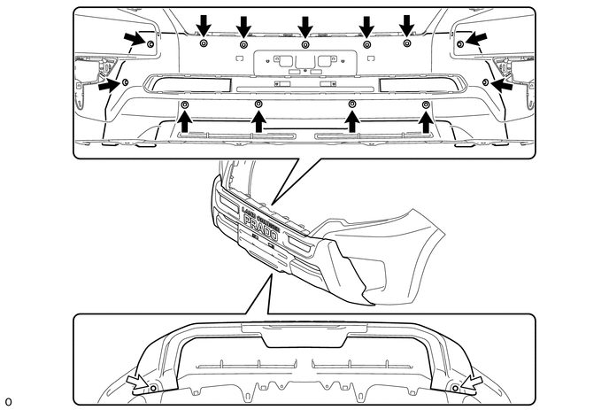
Attach the rib to install the front bumper guard assembly as shown in the illustration.
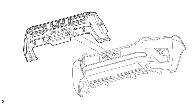
Install the 13 bolts.

|
Bolt | 
|
Clip |
Install the 2 clips.
53112E
2.INSTALL LOWER NO. 1 RADIATOR GRILLE
Attach the 20 claws to install the lower No. 1 radiator grille.
Install the screw.
82112
3.INSTALL NO. 2 ENGINE ROOM WIRE (w/ Fog Light)
Attach the 9 clamps to install the No. 2 engine room wire.
89347B
4.INSTALL FRONT CORNER ULTRASONIC SENSOR RETAINER (w/ TOYOTA Parking Assist-sensor System)
89341K
5.INSTALL FRONT CORNER ULTRASONIC SENSOR (w/ TOYOTA Parking Assist-sensor System)
89347C
6.INSTALL FRONT CENTER ULTRASONIC SENSOR RETAINER (w/ TOYOTA Parking Assist-sensor System)
- HINT:
-
Use the same procedure described for the front corner ultrasonic sensor retainer.
89341L
7.INSTALL FRONT CENTER ULTRASONIC SENSOR (w/ TOYOTA Parking Assist-sensor System)
- HINT:
-
Use the same procedure described for the front corner ultrasonic sensor.
85208A
8.INSTALL HEADLIGHT WASHER ACTUATOR SUB-ASSEMBLY LH (w/ Headlight Cleaner System)
85207A
9.INSTALL HEADLIGHT WASHER ACTUATOR SUB-ASSEMBLY RH (w/ Headlight Cleaner System)
- HINT:
-
Use the same procedure described for the LH side.
10.INSTALL NO. 1 HEADLIGHT CLEANER HOSE (w/ Headlight Cleaner System)
85045
11.INSTALL TYPE 1 HEADLIGHT WASHER NOZZLE SUB-ASSEMBLY LH (w/ Headlight Cleaner System)
85044
12.INSTALL TYPE 1 HEADLIGHT WASHER NOZZLE SUB-ASSEMBLY RH (w/ Headlight Cleaner System)
- HINT:
-
Use the same procedure described for the LH side.
52128B
13.INSTALL FRONT BUMPER HOLE COVER LH (w/o Fog Light)
Attach the 4 claws to install the front bumper hole cover LH.
52127D
14.INSTALL FRONT BUMPER HOLE COVER RH (w/o Fog Light)
- HINT:
-
Use the same procedure described for the LH side.
81482C
15.INSTALL FOG LIGHT COVER LH (w/ Fog Light, for Type A)
Attach the 4 claws to install the fog light cover LH.
81481E
16.INSTALL FOG LIGHT COVER RH (w/ Fog Light, for Type A)
- HINT:
-
Use the same procedure described for the LH side.
81482C
17.INSTALL FOG LIGHT COVER LH (w/ Fog Light, for Type B)
Attach the 3 claws to install the fog light cover LH.
Install the 3 outside moulding retainers.
81481E
18.INSTALL FOG LIGHT COVER RH (w/ Fog Light, for Type B)
- HINT:
-
Use the same procedure described for the LH side.
52126A
19.INSTALL FOG LIGHT MOUNTING BRACKET LH (w/ Fog Light)
Install the fog light mounting bracket LH with the 3 screws.
52125A
20.INSTALL FOG LIGHT MOUNTING BRACKET RH (w/ Fog Light)
- HINT:
-
Use the same procedure described for the LH side.
81220
21.INSTALL FOG LIGHT ASSEMBLY LH (w/ Fog Light)
81210A
22.INSTALL FOG LIGHT ASSEMBLY RH (w/ Fog Light)
- HINT:
-
Use the same procedure described for the LH side.
52149
23.INSTALL FRONT BUMPER INNER BRACKET (w/ Fog Light)
Attach the 3 claws to install the front bumper inner bracket.
76852B
24.INSTALL FRONT SPOILER LH (w/ Front Spoiler)
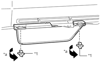
| *1 | Front Spoiler No. 1 Retainer |
| *a | 90° |
Turn the 2 front spoiler No. 1 retainers 90° in the direction indicated by the arrow in the illustration to install it to the front spoiler LH.
76851B
25.INSTALL FRONT SPOILER RH (w/ Front Spoiler)
- HINT:
-
Use the same procedure described for the LH side.
52114A
26.INSTALL FRONT BUMPER EXTENSION MOUNTING BRACKET (w/ Bracket)
Attach the 2 claws to install the front bumper extension mounting bracket.
Install the 2 screws.