RM27T0E
_52
Drivetrain
_053698
AC60F AUTOMATIC TRANSMISSION / TRANSAXLE
_0433833
SHIFT PADDLE SWITCH
G
AC60F AUTOMATIC TRANSMISSION / TRANSAXLE SHIFT PADDLE SWITCH INSPECTION
PROCEDURE

 84610F
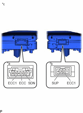
1.INSPECT TRANSMISSION SHIFT SWITCH ASSEMBLY
a.
2.25,3.333 2.5,3
true
2.917,3.333 2.646,3.01
true
0.5,3.333 0.74,3.094
true
0.896,3.333 0.896,3.104
true
1.25,3.333 1.042,3.094
true
0.292,2.542 0.458,2.708
0.167,0.167
10
false
*a
2.052,2.552 2.219,2.719
0.167,0.167
10
false
*b
2.146,3.354 2.479,3.521
0.333,0.167
10
false
SUP
2.771,3.354 3.188,3.521
0.417,0.167
10
false
ECC1
1.167,3.354 1.5,3.521
0.333,0.167
10
false
SDN
0.792,3.354 1.125,3.521
0.333,0.167
10
false
ECC
0.333,3.354 0.75,3.521
0.417,0.167
10
false
ECC1
0.083,0.083 0.25,0.25
0.167,0.167
10
false
*c
| *a | for Transmission Shift Switch Assembly LH Side ("-") |
| *b | for Transmission Shift Switch Assembly RH Side ("+") |
| *c | Component without harness connected
(Transmission Shift Switch Assembly) |
Measure the resistance according to the value(s) in the table below.
- Standard Resistance:
Tester Connection Switch Condition Specified Condition 2(SDN) - 3(ECC) Pull continuously "-" (Down shift) Below 2.5 Ω 2(SDN) - 4(ECC1) Pull continuously "-" (Down shift) Below 2.5 Ω 2(SDN) - 3(ECC) Release "-" (Down shift) 1 MΩ or higher 2(SDN) - 4(ECC1) Release "-" (Down shift) 1 MΩ or higher 3(SUP) - 2(ECC1) Pull continuously "+" (Up shift) Below 2.5 Ω 3(SUP) - 2(ECC1) Release "+" (Up shift) 1 MΩ or higher 3(ECC) - 4(ECC1) Always (Down shift) Below 2.5 Ω
If the resistance value is not as specified, replace the transmission shift switch assembly.
84523
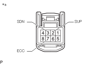
2.INSPECT NO. 1 SWITCH WIRE
a.
Connect the No. 1 switch wire connector to the 2 transmission shift switch assemblies.
b.
0.917,0.75 1.083,0.75
1.083,0.75 1.573,1.052
true
2.5,0.75 2.333,0.75
2.333,0.75 1.844,1.052
true
0.917,1.75 1.083,1.75
1.083,1.75 1.573,1.365
true
0.083,0.083 0.333,0.25
0.25,0.167
10
false
*a
0.583,0.667 1,0.833
0.417,0.167
10
false
SDN
2.542,0.667 2.958,0.833
0.417,0.167
10
false
SUP
0.583,1.667 1,1.833
0.417,0.167
10
false
ECC
| *a | Component without harness connected
(No. 1 switch wire (to Spiral Cable Sub-assembly)) |
Measure the resistance according to the value(s) in the table below.
- Standard Resistance:
Tester Connection Switch Condition Specified Condition 3(SDN) - 7(ECC) Pull continuously "-" (Down shift) Below 2.5 Ω 3(SDN) - 7(ECC) Release "-" (Down shift) 1 MΩ or higher 2(SUP) - 7(ECC) Pull continuously "+" (Up shift) Below 2.5 Ω 2(SUP) - 7(ECC) Release "+" (Up shift) 1 MΩ or higher
If the resistance value is not as specified, replace the No. 1 switch wire.