Home › Vehicle Interior › LIGHTING (INT) › LIGHTING SYSTEM (except 5L-E) › from 2020.08
RM27T0E _58 Vehicle Interior _053732 LIGHTING (INT) _0326432 LIGHTING SYSTEM(except 5L-E) J

LIGHTING (INT)  LIGHTING SYSTEM(except 5L-E)  Interior Light Auto Cut Circuit  


DESCRIPTION

w/o Stop and Start System:

When the battery saving control operates, the main body ECU (multiplex network body ECU) controls the operation of the DOME relay that is built into the No. 1 integration relay to turn off the interior lights.


w/ Stop and Start System:

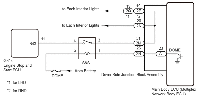
When the battery saving control operates, the main body ECU (multiplex network body ECU) controls the operation of the S&S relay that is built into the engine room relay block to turn off the interior lights.


WIRING DIAGRAM
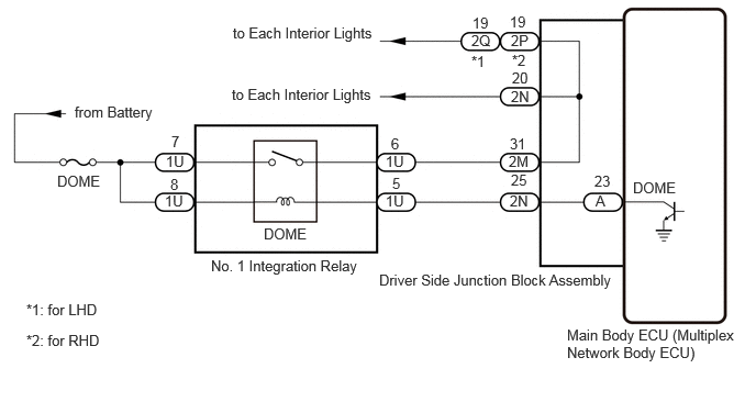
w/o Stop and Start System:
E456186E01
5.375,3.094 7.094,3.438 1.719,0.344 10 false Main Body ECU (Multiplex Network Body ECU) 3.594,2.573 5.938,2.844 2.344,0.271 10 false Driver Side Junction Block Assembly 6,1.698 6.667,2.052 0.667,0.354 10 false DOME 5.635,1.635 6.302,1.99 0.667,0.354 10 false 23 5.646,1.823 6.313,2.177 0.667,0.354 10 false A 2.208,0.229 3.948,0.604 1.74,0.375 10 false to Each Interior Lights 0.708,0.979 2.448,1.354 1.74,0.375 10 false from Battery 0.542,1.635 2.281,2.01 1.74,0.375 10 false DOME 2.5,2.135 4.24,2.51 1.74,0.375 10 false DOME 1.573,1.448 3.313,1.823 1.74,0.375 10 false 1U 3.719,1.656 5.458,2.031 1.74,0.375 10 false 5 3.708,1.281 5.448,1.656 1.74,0.375 10 false 6 1.615,1.667 3.354,2.042 1.74,0.375 10 false 8 1.625,1.26 3.365,1.635 1.74,0.375 10 false 7 2,2.438 3.688,2.833 1.688,0.396 10 false No. 1 Integration Relay 4.833,1.823 6.563,2.188 1.729,0.365 10 false 2N 4.844,1.625 6.583,2 1.74,0.375 10 false 25 2.198,0.813 3.938,1.188 1.74,0.375 10 false to Each Interior Lights 0.25,2.854 1.938,3.25 1.688,0.396 10 false *1: for LHD 0.25,3.146 1.938,3.542 1.688,0.396 10 false *2: for RHD 4.833,1.281 6.573,1.656 1.74,0.375 10 false 31 4.823,1.448 6.552,1.813 1.729,0.365 10 false 2M 4.844,0.833 6.573,1.198 1.729,0.365 10 false 2N 4.854,0.656 6.583,1.021 1.729,0.365 10 false 20 4.854,0.49 6.583,0.854 1.729,0.365 10 false *2 4.833,0.125 6.573,0.5 1.74,0.375 10 false 19 4.479,0.135 6.219,0.51 1.74,0.375 10 false 19 4.844,0.302 6.573,0.667 1.729,0.365 10 false 2P 4.469,0.302 6.198,0.667 1.729,0.365 10 false 2Q 1.563,1.823 3.302,2.198 1.74,0.375 10 false 1U 3.656,1.823 5.396,2.198 1.74,0.375 10 false 1U 3.656,1.448 5.396,1.823 1.74,0.375 10 false 1U 4.469,0.5 6.198,0.865 1.729,0.365 10 false *1

w/ Stop and Start System:
E455943E01
5.375,3.094 7.094,3.438 1.719,0.344 10 false Main Body ECU (Multiplex Network Body ECU) 3.594,2.573 5.938,2.844 2.344,0.271 10 false Driver Side Junction Block Assembly 6,1.698 6.667,2.052 0.667,0.354 10 false DOME 5.635,1.635 6.302,1.99 0.667,0.354 10 false 23 5.646,1.823 6.313,2.177 0.667,0.354 10 false A 2.208,0.229 3.948,0.604 1.74,0.375 10 false to Each Interior Lights 2.667,2.438 4.406,2.813 1.74,0.375 10 false from Battery 1.042,1.469 2.781,1.844 1.74,0.375 10 false B43 2.917,2.156 4.656,2.531 1.74,0.375 10 false S&S 2.635,1.354 4.375,1.729 1.74,0.375 10 false 5 3.479,1.344 5.219,1.719 1.74,0.375 10 false 3 2.635,1.708 4.375,2.083 1.74,0.375 10 false 2 1.458,1.302 3.198,1.677 1.74,0.375 10 false 11 4.833,1.823 6.563,2.188 1.729,0.365 10 false 2N 4.844,1.625 6.583,2 1.74,0.375 10 false 25 2.198,0.813 3.938,1.188 1.74,0.375 10 false to Each Interior Lights 0.25,2.854 1.938,3.25 1.688,0.396 10 false *1: for LHD 0.25,3.146 1.938,3.542 1.688,0.396 10 false *2: for RHD 4.833,1.281 6.573,1.656 1.74,0.375 10 false 31 4.823,1.448 6.552,1.813 1.729,0.365 10 false 2M 4.844,0.833 6.573,1.198 1.729,0.365 10 false 2N 4.854,0.656 6.583,1.021 1.729,0.365 10 false 20 4.854,0.49 6.583,0.854 1.729,0.365 10 false *2 4.833,0.125 6.573,0.5 1.74,0.375 10 false 19 4.479,0.135 6.219,0.51 1.74,0.375 10 false 19 4.844,0.302 6.573,0.667 1.729,0.365 10 false 2P 4.469,0.302 6.198,0.667 1.729,0.365 10 false 2Q 0.125,2.073 1.865,2.448 1.74,0.375 10 false G314 4.469,0.5 6.198,0.865 1.729,0.365 10 false *1 0.125,2.24 1.167,2.573 1.042,0.333 10 false Engine Stop and Start ECU 3.479,1.719 5.219,2.094 1.74,0.375 10 false 1 1.833,2.615 3.573,2.99 1.74,0.375 10 false DOME

CAUTION / NOTICE / HINT

NOTICE:

Before replacing the main body ECU (multiplex network body ECU), refer to Service Bulletin.


PROCEDURE

1.PERFORM ACTIVE TEST USING GTS
a.

All of the interior lights turn on.


b.

Perform the Active Test according to the display on the GTS.

Click hereVehicle Interior>LIGHTING (INT)>LIGHTING SYSTEM (except 5L-E)>DATA LIST / ACTIVE TEST

Main Body
Tester Display Measurement Item Control Range Diagnostic Note
Relay for Interior Light Auto Cut Function DOME relay OFF or ON OFF: DOME relay on (interior lights turn on)
ON: DOME relay off (interior lights turn off)

OK:

All of the interior lights turn off when ON is selected.


Result:
Result Proceed to
OK A
NG (w/o Stop and Start System) B
NG (w/ Stop and Start System) C


A

PROCEED TO NEXT SUSPECTED AREA SHOWN IN PROBLEM SYMPTOMS TABLE

B

2.INSPECT NO. 1 INTEGRATION RELAY

C

5.INSPECT S&S RELAY
2.INSPECT NO. 1 INTEGRATION RELAY
a.
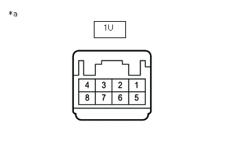
E377411C01
1.427,0.323 1.906,0.573 0.479,0.25 0.135,0.135 0.448,0.292 0.313,0.156 10 false *a 1.573,0.354 1.885,0.51 0.313,0.156 10 false 1U
*a Component without harness connected
(No. 1 Integration Relay)


Remove the No. 1 integration relay.


b.

Measure the resistance according to the value(s) in the table below.

Standard Resistance:
Tester Connection Condition Specified Condition
1U-6 - 1U-7 Battery not connected to 1U-5 and 1U-8 Below 1 Ω
Battery positive (+) → 1U-8
Battery negative (-) → 1U-5
10 kΩ or higher


Result:
Proceed to
OK
NG


OK

3.CHECK HARNESS AND CONNECTOR (NO. 1 INTEGRATION RELAY - DRIVER SIDE JUNCTION BLOCK ASSEMBLY AND BATTERY)

NG

REPLACE NO. 1 INTEGRATION RELAY

3.CHECK HARNESS AND CONNECTOR (NO. 1 INTEGRATION RELAY - DRIVER SIDE JUNCTION BLOCK ASSEMBLY AND BATTERY)
a.

Remove the No. 1 integration relay.


b.

Disconnect the 2M and 2N driver side junction block assembly connectors.


c.

Measure the resistance according to the value(s) in the table below.

Standard Resistance:
Tester Connection Condition Specified Condition
1U-5 - 2N-25 Always Below 1 Ω
1U-6 - 2M-31 Always Below 1 Ω
1U-5 or 2N-25 - Body ground Always 10 kΩ or higher
1U-6 or 2M-31 - Body ground Always 10 kΩ or higher


d.

Measure the voltage according to the value(s) in the table below.

Standard Voltage:
Tester Connection Condition Specified Condition
1U-7 - Body ground Always 11 to 14 V
1U-8 - Body ground Always 11 to 14 V


Result:
Proceed to
OK
NG


OK

4.CHECK DRIVER SIDE JUNCTION BLOCK ASSEMBLY

NG

REPAIR OR REPLACE HARNESS OR CONNECTOR

4.CHECK DRIVER SIDE JUNCTION BLOCK ASSEMBLY
a.

Remove the driver side junction block assembly.

Click herePower Source / Network>POWER DISTRIBUTION>MAIN BODY ECU>REMOVAL
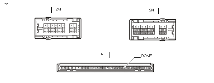
E377725C01
3.208,1.75 3.656,1.958 0.448,0.208 4.854,0.26 5.302,0.469 0.448,0.208 1.719,0.229 2.167,0.438 0.448,0.208 4.135,2.292 4.49,1.938 4.49,1.938 4.698,1.938 true 0.146,0.063 0.458,0.219 0.313,0.156 10 false *a 3.375,1.75 3.729,2.01 0.354,0.26 10 false A 5,0.271 5.313,0.427 0.313,0.156 10 false 2N 1.865,0.24 2.177,0.396 0.313,0.156 10 false 2M 4.74,1.813 5.188,2.083 0.448,0.271 10 false DOME
*a Component without harness connected
(Driver Side Junction Block Assembly)
- -


b.

Remove the main body ECU (multiplex network body ECU) from the driver side junction block assembly.

Click herePower Source / Network>POWER DISTRIBUTION>MAIN BODY ECU>REMOVAL


c.

Measure the resistance according to the value(s) in the table below.

Standard Resistance:
Tester Connection Condition Specified Condition
2N-25 - A-23 (DOME) Always Below 1 Ω
2M-31 - 2N-20 Always Below 1 Ω


Result:
Proceed to
OK
NG


OK

REPLACE MAIN BODY ECU (MULTIPLEX NETWORK BODY ECU)

NG

REPLACE DRIVER SIDE JUNCTION BLOCK ASSEMBLY

5.INSPECT S&S RELAY
a.
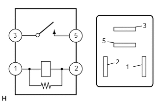
E277744E01
3.01,1.375 2.823,1.417 false 2.281,1.375 2.427,1.333 false 2.417,0.906 2.281,0.885 false 2.875,0.573 3.01,0.552 false 1.573,0.667 1.719,0.844 0.146,0.177 10 false 5 1.583,1.365 1.729,1.542 0.146,0.177 10 false 2 0.281,0.667 0.427,0.844 0.146,0.177 10 false 3 0.292,1.365 0.438,1.542 0.146,0.177 10 false 1 2.167,0.781 2.313,0.958 0.146,0.177 10 false 5 2.458,1.229 2.604,1.406 0.146,0.177 10 false 2 3.031,0.458 3.177,0.635 0.146,0.177 10 false 3 2.667,1.333 2.813,1.51 0.146,0.177 10 false 1

Remove the S&S relay.


b.

Measure the resistance according to the value(s) in the table below.

Standard Resistance:
Tester Connection Condition Specified Condition
3 - 5 Battery voltage applied to terminals 1 and 2 Below 1 Ω
Battery voltage not applied to terminals 1 and 2 10 kΩ or higher


Result:
Proceed to
OK
NG


OK

6.CHECK HARNESS AND CONNECTOR (S&S RELAY - BATTERY)

NG

REPLACE S&S RELAY

6.CHECK HARNESS AND CONNECTOR (S&S RELAY - BATTERY)
a.
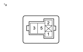
B472073C15
0.156,0.115 0.469,0.313 0.313,0.198 10 false *a
*a Front view of wire harness connector
(to S&S Relay)


Remove the S&S relay.


b.

Measure the voltage according to the value(s) in the table below.

Standard Voltage:
Tester Connection Condition Specified Condition
S&S relay terminal 2 - Body ground Always 11 to 14 V


Result:
Proceed to
OK
NG


OK

7.CHECK HARNESS AND CONNECTOR (S&S RELAY - DRIVER SIDE JUNCTION BLOCK ASSEMBLY AND ENGINE STOP AND START ECU)

NG

REPAIR OR REPLACE HARNESS OR CONNECTOR

7.CHECK HARNESS AND CONNECTOR (S&S RELAY - DRIVER SIDE JUNCTION BLOCK ASSEMBLY AND ENGINE STOP AND START ECU)
a.

Remove the S&S relay.


b.

Disconnect the 2M and 2N driver side junction block assembly connectors.


c.

Disconnect the G314 engine stop and start ECU connector.


d.

Measure the resistance according to the value(s) in the table below.

Standard Resistance:
Tester Connection Condition Specified Condition
S&S relay terminal 1 - 2N-25 Always Below 1 Ω
S&S relay terminal 3 - 2M-31 Always Below 1 Ω
S&S relay terminal 5 - G314-11 (B43) Always Below 1 Ω
S&S relay terminal 1 or 2N-25 - Body ground Always 10 kΩ or higher
S&S relay terminal 3 or 2M-31 - Body ground Always 10 kΩ or higher
S&S relay terminal 5 or G314-11 (B43) - Body ground Always 10 kΩ or higher


Result:
Proceed to
OK
NG


OK

8.CHECK DRIVER SIDE JUNCTION BLOCK ASSEMBLY

NG

REPAIR OR REPLACE HARNESS OR CONNECTOR

8.CHECK DRIVER SIDE JUNCTION BLOCK ASSEMBLY
a.

Remove the driver side junction block assembly.

Click herePower Source / Network>POWER DISTRIBUTION>MAIN BODY ECU>REMOVAL

E377725C01
3.208,1.75 3.656,1.958 0.448,0.208 4.854,0.26 5.302,0.469 0.448,0.208 1.719,0.229 2.167,0.438 0.448,0.208 4.135,2.292 4.49,1.938 4.49,1.938 4.698,1.938 true 0.146,0.063 0.458,0.219 0.313,0.156 10 false *a 3.375,1.75 3.729,2.01 0.354,0.26 10 false A 5,0.271 5.313,0.427 0.313,0.156 10 false 2N 1.865,0.24 2.177,0.396 0.313,0.156 10 false 2M 4.74,1.813 5.188,2.083 0.448,0.271 10 false DOME
*a Component without harness connected
(Driver Side Junction Block Assembly)
- -


b.

Remove the main body ECU (multiplex network body ECU) from the driver side junction block assembly.

Click herePower Source / Network>POWER DISTRIBUTION>MAIN BODY ECU>REMOVAL


c.

Measure the resistance according to the value(s) in the table below.

Standard Resistance:
Tester Connection Condition Specified Condition
2N-25 - A-23 (DOME) Always Below 1 Ω
2M-31 - 2N-20 Always Below 1 Ω


Result:
Proceed to
OK
NG


OK

REPLACE MAIN BODY ECU (MULTIPLEX NETWORK BODY ECU)

NG

REPLACE DRIVER SIDE JUNCTION BLOCK ASSEMBLY