Home › Vehicle Interior › METER / GAUGE / DISPLAY › METER / GAUGE SYSTEM › from 2020.08
RM27T0E _58 Vehicle Interior _053733 METER / GAUGE / DISPLAY _0261082 METER / GAUGE SYSTEM J

METER / GAUGE / DISPLAY  METER / GAUGE SYSTEM  Entire Combination Meter does not Operate  


DESCRIPTION

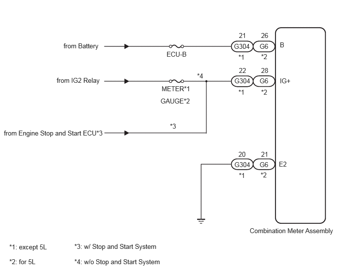
This circuit is the power source circuit for the meter. This circuit provides two types of power sources; one is a constant power source mainly used as a backup power source, and the other is an IG power source mainly used for signal transmission. The constant power source is mainly used as a backup power source for the meter CPU, however, it is also used for CAN communication. If a voltage of 12 V is not applied to terminal IG+ when turn the ignition switch to ON, the indicator will not operate.

WIRING DIAGRAM
B598743E02
1.344,0.885 2.292,1.115 0.948,0.229 10 false from Battery 1.198,1.615 2.219,1.875 1.021,0.26 10 false from IG2 Relay 3.521,1.063 4.094,1.302 0.573,0.24 10 false ECU-B 3.417,1.792 4.177,2.031 0.76,0.24 10 false METER*1 5.052,0.667 5.365,0.896 0.313,0.229 10 false 21 5.521,0.667 5.781,0.896 0.26,0.229 10 false 26 5.49,0.896 5.844,1.104 0.354,0.208 10 false G6 4.948,0.896 5.417,1.104 0.469,0.208 10 false G304 5.521,1.406 5.781,1.635 0.26,0.229 10 false 28 5.052,1.406 5.406,1.615 0.354,0.208 10 false 22 4.958,1.625 5.427,1.833 0.469,0.208 10 false G304 5.49,1.625 5.844,1.833 0.354,0.208 10 false G6 5.521,3.177 5.875,3.385 0.354,0.208 10 false 21 5.042,3.177 5.396,3.385 0.354,0.208 10 false 20 4.958,3.396 5.396,3.594 0.438,0.198 10 false G304 5.49,3.396 5.844,3.604 0.354,0.208 10 false G6 5.51,3.615 5.75,3.854 0.24,0.24 10 false *2 5.052,3.625 5.271,3.833 0.219,0.208 10 false *1 5.042,1.865 5.302,2.073 0.26,0.208 10 false *1 5.521,1.865 5.792,2.073 0.271,0.208 10 false *2 5.521,1.115 5.771,1.313 0.25,0.198 10 false *2 5.042,1.125 5.323,1.354 0.281,0.229 10 false *1 5.917,0.865 6.167,1.063 0.25,0.198 10 false B 5.917,1.625 6.229,1.844 0.313,0.219 10 false IG+ 5.896,3.385 6.167,3.594 0.271,0.208 10 false E2 5.281,4.792 7.125,5.042 1.844,0.25 10 false Combination Meter Assembly 0.198,5.135 1.385,5.396 1.188,0.26 10 false *1: except 5L 0.198,5.448 1.063,5.677 0.865,0.229 10 false *2: for 5L 0.083,2.729 2.698,3.469 2.615,0.74 10 false from Engine Stop and Start ECU*3 1.573,5.125 3.958,5.354 2.385,0.229 10 false *3: w/ Stop and Start System 1.573,5.448 3.958,5.677 2.385,0.229 10 false *4: w/o Stop and Start System 3.594,2.583 3.813,2.792 0.219,0.208 10 false *3 4.167,1.521 4.385,1.729 0.219,0.208 10 false *4 3.396,2.052 4.156,2.292 0.76,0.24 10 false GAUGE*2

CAUTION / NOTICE / HINT

NOTICE:
·

Inspect the fuses for circuits related to this system before performing the following inspection procedure.

·

When replacing the combination meter assembly, always replace it with a new one. If a combination meter assembly which was installed to another vehicle is used, the information stored in it will not match the information from the vehicle and a DTC may be stored.


PROCEDURE
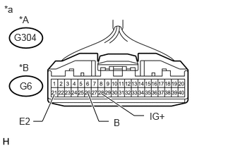
1.CHECK HARNESS AND CONNECTOR (COMBINATION METER ASSEMBLY - BATTERY AND BODY GROUND)
a.
E380678E03
0.802,1.396 0.625,1.792 0.625,1.792 0.49,1.792 true 1.292,1.365 1.458,1.792 1.458,1.792 1.604,1.792 true 1.5,1.385 1.979,1.708 1.979,1.708 2.125,1.708 true 0.063,0.052 0.375,0.25 0.313,0.198 10 false *a 0.208,0.469 0.667,0.667 0.458,0.198 10 false G304 0.292,1.188 0.583,1.396 0.292,0.208 10 false G6 0.281,0.208 0.594,0.406 0.313,0.198 10 false *A 0.281,0.917 0.594,1.115 0.313,0.198 10 false *B 0.281,1.708 0.594,1.906 0.313,0.198 10 false E2 1.677,1.729 1.99,1.927 0.313,0.198 10 false B 2.208,1.635 2.521,1.833 0.313,0.198 10 false IG+

Disconnect the combination meter assembly connectors.


b.

Measure the resistance according to the value(s) in the table below.

Standard Resistance:
Standard Voltage (except 5L-E)
Tester Connection Condition Specified Condition
G304-20(E2) - Body ground Always Below 1 Ω

Standard Voltage (for 5L-E)
Tester Connection Condition Specified Condition
G6-21 (E2) - Body ground Always Below 1 Ω


c.

Measure the voltage according to the value(s) in the table below.

*1: w/ Stop and Start System

*2: w/o Stop and Start System


Standard Voltage (except 5L-E):
Tester Connection Condition Specified Condition
G304-22 (IG+) - Body ground Ignition switch ON 10.5 to 16 V*1
11 to 14 V*2
G304-21 (B) - Body ground Always 11 to 14 V


Standard Voltage (for 5L-E):
Tester Connection Condition Specified Condition
G6-28 (IG+) - Body ground Ignition switch ON 11 to 14 V
G6-26 (B) - Body ground Always 11 to 14 V


Text in Illustration
*A except 5L-E
*B for 5L-E
*a Front view of wire harness connector
(to Combination Meter Assembly


OK

REPLACE COMBINATION METER ASSEMBLY

NG

REPAIR OR REPLACE HARNESS OR CONNECTOR