Starter Signal Circuit
Circuit diagnosis · Vehicles built from Jan 2012
Versions by build date: Sep 2011 – Dec 2011 from Jan 2012
DESCRIPTION
While the engine is being cranked, current flows from terminal ST2 of the ignition switch to the park/neutral position switch and also flows to terminal STA of the ECM (STA Signal).WIRING DIAGRAM
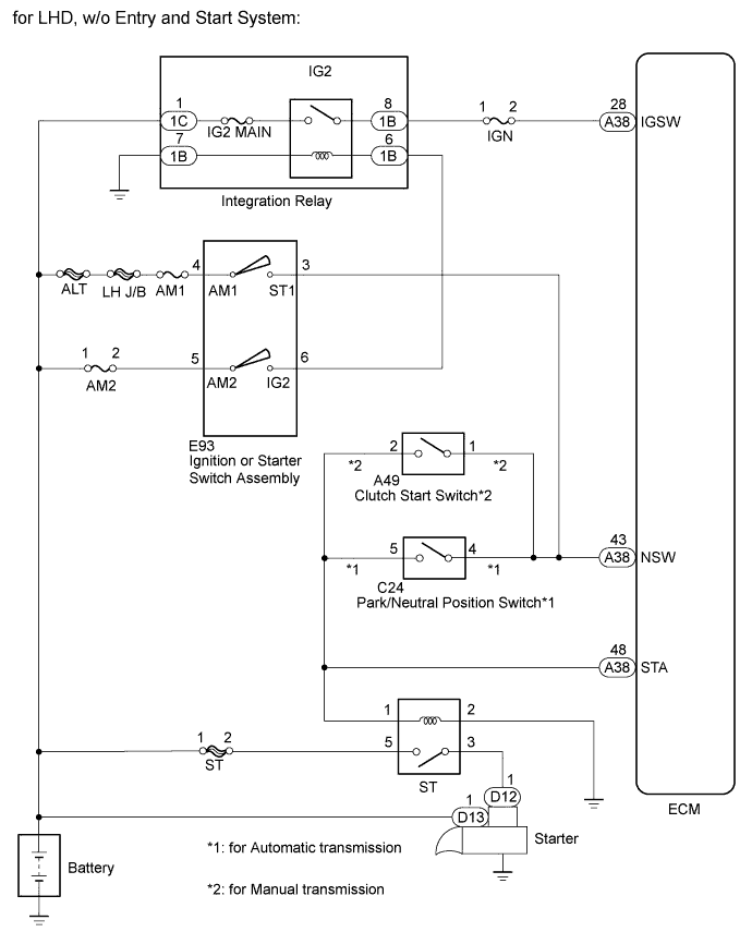

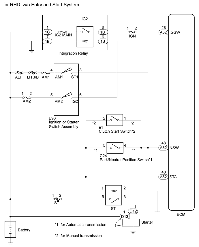
INSPECTION PROCEDURE
- NOTICE:
- Inspect the fuses of circuits related to this system before performing the following inspection procedure.
- After replacing the ECM, the new ECM needs registration (Click here) and initialization (Click here).
- Inspect the fuses of circuits related to this system before performing the following inspection procedure.
- HINT:
- This chart is based on the premise that the engine can crank normally. If the engine cannot crank normally, proceed to Problem Symptoms Table (Click here).
| 1. READ VALUE USING INTELLIGENT TESTER (STARTER SIGNAL) |

Connect the intelligent tester to the DLC3.
Turn the ignition switch to ON.
Turn the tester on.
Enter the following menus: Powertrain / Engine / Data List / Starter Signal.
Read the value.
- OK:
Ignition Switch Condition
Starter Signal
ON
OFF
START
ON
|
|
||||

| OK | ||
 |
||
| ||
| 2. CHECK HARNESS AND CONNECTOR (STARTER RELAY [ST] - ECM) |
Remove the ST relay from the engine room relay block.
Disconnect the ECM connector.
Measure the resistance according to the value(s) in the table below.
- Standard Resistance:
for LHD Tester Connection
Condition
Specified Condition
ST relay terminal 1 - A38-48 (STA)
Always
Below 1 Ω
for RHD Tester Connection
Switch Condition
Specified Condition
ST relay terminal 1 - A52-48 (STA)
Always
Below 1 Ω
Reinstall the starter relay (ST).
Reconnect the ECM connector.
|
|
||||

| OK | ||
|
||
| ||