SYSTEM DESCRIPTION
Troubleshooting · Vehicles built Sep 2011 – Dec 2011
| NAVIGATION SYSTEM OUTLINE |
Vehicle position tracking methods
It is essential that the navigation system correctly tracks the current vehicle position and displays it on the map. There are 2 methods to track the current vehicle position; autonomous (dead reckoning) and GPS* (satellite) navigation. Both navigation methods are used in conjunction with each other.
*GPS (Global Positioning System)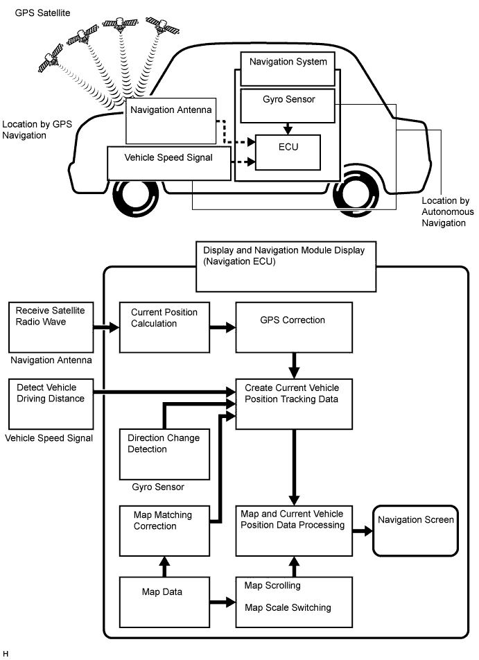

Operation
Description
Vehicle Position Calculation
The display and navigation module display calculates the current vehicle position (direction and current position) using the direction deviation signal from the gyro sensor and the running distance signal from the vehicle speed sensor and creates the driving route.
Map Display Processing
The display and navigation module display displays the vehicle track on the map by processing the vehicle position data, vehicle running track and map data from the map disc.
Map Matching
The map data from the map disc is compared to the vehicle position and running track data. Then, the vehicle position is matched with the nearest road.
GPS Correction
The vehicle position is matched to the position measured by GPS. Then, the GPS measurement position data is compared with the vehicle position and running track data. If the position is widely different, the GPS measurement position is used.
Distance Correction
The vehicle speed signal includes the error caused by tire wear and slippage between the tires and road surface. Distance correction is performed to account for this. The display and navigation module display automatically offsets the signal to make up for the difference between it and the distance data of the map. The offset is automatically updated.
- HINT:
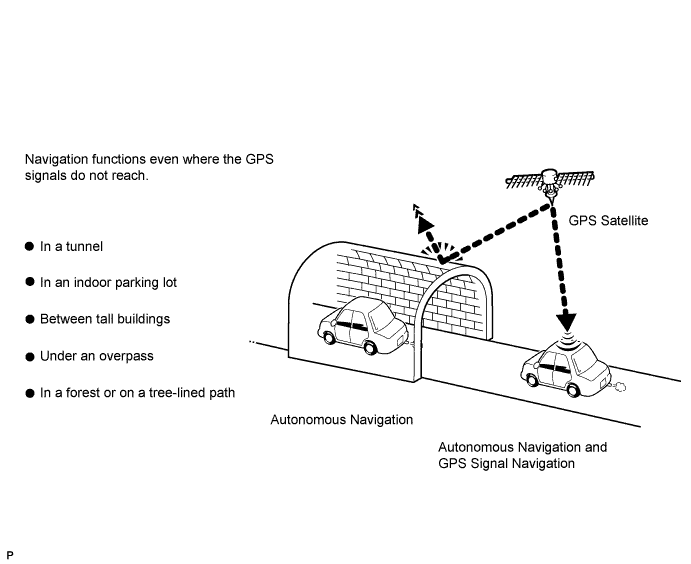
- The combination of autonomous and GPS navigation makes it possible to display the vehicle position even when the vehicle is in places where the GPS cannot receive a signal. When only autonomous navigation is used, however, the mapping accuracy may slightly decrease.
Autonomous navigation
This method determines the relative vehicle position based on the running track determined by the gyro located in the display and navigation module display and the vehicle speed sensors signal.Gyro sensor
Used to calculate the direction by detecting angular velocity. It is located in the display and navigation module display.Vehicle speed sensor signal
Used to calculate the vehicle running distance.
GPS* navigation (Satellite navigation)
This method detects the absolute vehicle position using radio waves from GPS satellites.
*GPS satellites were launched by the U.S. Department of Defense for military purposes.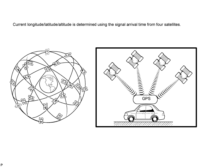
Number of Satellites
Measurement
Description
2 or less
Measurement impossible
Vehicle position cannot be obtained because the number of satellites is not enough.
3
2-dimensional measurement is possible
Vehicle position is obtained based on the current longitude and latitude. (This is less precise than 3-dimensional measurement.)
4
3-dimensional measurement is possible
Vehicle position is obtained based on the current longitude, latitude and altitude.
Map matching
The current driving route is calculated by autonomous navigation (according to the gyro sensor and vehicle speed sensor) and GPS navigation. This information is then compared with possible road shapes from the map data in the map disc and the vehicle position is set onto the most appropriate road.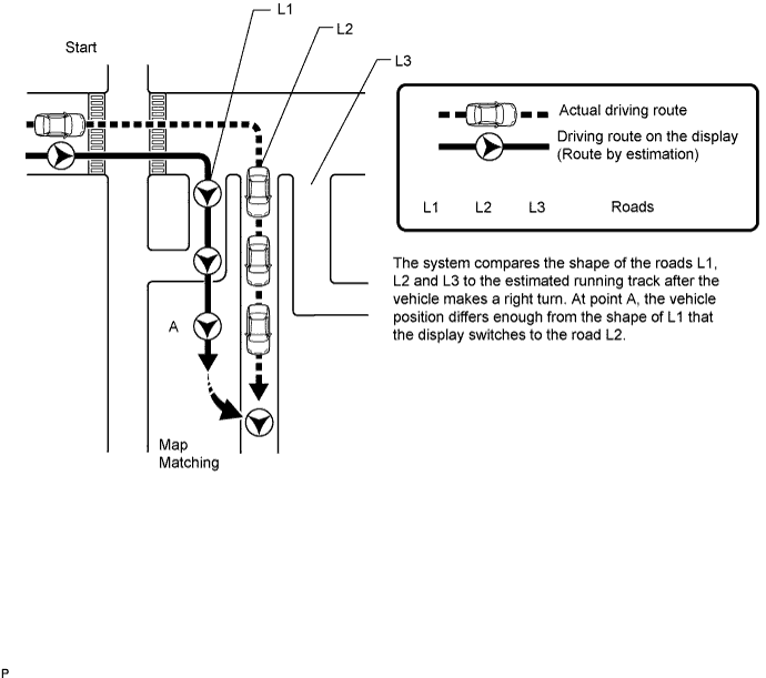
Touch switch
Touch switches are touch-sensitive (interactive) switches operated by touching the screen. When a switch is pressed, the outer glass bends to contact the inner glass at the pressed position. By doing this, the voltage ratio is measured and the pressed position is detected.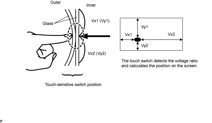
| DVD (Digital Versatile Disc) PLAYER OUTLINE (DVD Changer) |
The DVD player can only play DVD videos, DVD audio and video CDs that have any of the following marks:

Precaution for use of discs
- NOTICE:
- PAL or SECAM color television standard discs cannot be played (only NTSC discs can be played).
- Keep the discs away from dirt. Be careful not to damage the discs or leave fingerprints on them.
- Hold discs by the outer edge and center hole with the label side up.
- Leaving the disc exposed halfway out of the slot for a long time after pressing the disc eject button may cause deformation of the disc, making the disc unusable.
- Do not use odd-shaped CDs because these may cause player malfunctions.
- Do not use discs whose recording portion is transparent or translucent because they may not be inserted, ejected or played normally.
- DualDiscs that combine DVD recorded material on one side with CD digital audio material on the other cannot be played.
- PAL or SECAM color television standard discs cannot be played (only NTSC discs can be played).
Cleaning
- NOTICE:
- Do not use a lens cleaner because it may cause a malfunction in the pickup portion of the player.
If dirt is on the disc surface, wipe it clean with a soft dry cloth such as an eyeglass cleaner for plastic lenses from the inside to the outside in a radial direction.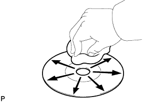
- NOTICE:
- Pressing on the disc by hand or rubbing the disc with a hard cloth may scratch the disc surface.
- Use of solvent such as a record spray, antistatic agent, alcohol, benzine and thinner or a chemical cloth may cause damage to the disc, making the disc unusable.
- Pressing on the disc by hand or rubbing the disc with a hard cloth may scratch the disc surface.
| "Bluetooth" OUTLINE |
"Bluetooth" is a trademark owned by Bluetooth SIG. Inc.
"Bluetooth" is a new wireless connection technology that uses the 2.4 GHz frequency band.
- HINT:
- The communication performance of "Bluetooth" may vary depending on obstructions or radio wave conditions between communication devices, electromagnetic radiation, communication device sensitivity or antenna capacity.
Hands-free function
The "Bluetooth" built-in radio receiver and a "Bluetooth" compatible cellular phone*1 can be connected using a "Bluetooth" wireless connection. This enables use of the hands-free function on the cellular phone even the phone may be in a pocket or bag. For this reason, it is not necessary to use a connector or cable to connect the cellular phone.
*1: Some versions of "Bluetooth" compatible cellular phones may not function.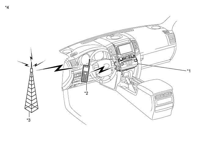
Text in Illustration *1
Radio Receiver Assembly
(Built-in "Bluetooth" Receiver Antenna)
*2
Cellular Phone
("Bluetooth" Type)
*3
Cellular Tower
*4
Example:
| VEHICLE CUSTOMIZATION OUTLINE |
Customization of functions can be performed on the multi display screen. Refer to the owner's manual for further information on customizable items for the navigation system.
- HINT:
- Items available for customization via the navigation system can be performed by using the intelligent tester.
- Some customize parameters displayed on the intelligent tester will be displayed on the "Vehicle Customization" screen for the navigation system. Users can customize these items.
- Items available for customization via the navigation system can be performed by using the intelligent tester.
| COMMUNICATION SYSTEM |
MOST Network Outline
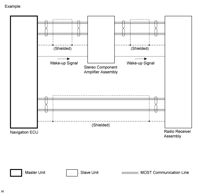
Navigation system components communicate with each other via the MOST network.
The MOST network uses a shielded twisted pair of wires for its communication lines.
The master unit of the MOST network is the display and navigation module display (navigation ECU).
MOST communication lines connect each slave unit centering around the master unit to form a MOST network ring.
The master unit sends a wake-up signal to activate each slave unit connected to the MOST network.
- HINT:
- If a short or open circuit occurs in the MOST circuit, communication will be interrupted and the system will not operate normally.
AVC-LAN Outline
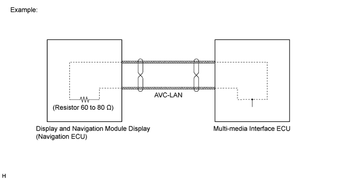
Components of the navigation system communicate with each other via the AVC-LAN.
The AVC-LAN uses a twisted pair of wires for its communication lines.
The master unit of the AVC-LAN is the display and navigation module display (navigation ECU).
- HINT:
- The display and navigation module display (navigation ECU) has enough resistance (60 to 80 Ω) necessary for communication.
- If a short or open circuit occurs in the AVC-LAN circuit, communication is interrupted and the system will not operate normally.
- The display and navigation module display (navigation ECU) has enough resistance (60 to 80 Ω) necessary for communication.
| DIAGNOSTIC FUNCTION OUTLINE |
The navigation system has a diagnostic function (the result will be displayed on the master unit or the intelligent tester).
| DIAGNOSIS DISPLAY DETAILED DESCRIPTION |
- HINT:
- This section contains a detailed description of displays in diagnostic mode.
- Illustrations may differ from the actual vehicle screen depending on the device settings and options. Therefore, some detailed areas may not be shown exactly the same as on the actual vehicle screen.
- This section contains a detailed description of displays in diagnostic mode.
Service Menu Screen
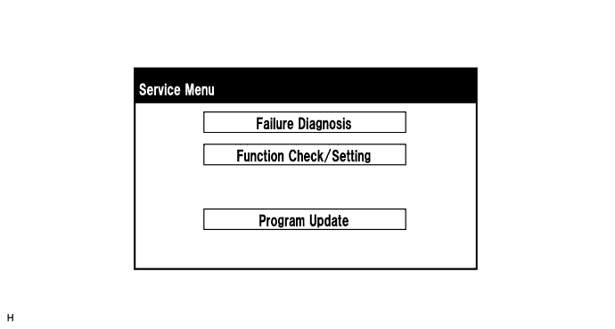
- HINT:
- Each item is grayed out or not displayed based on the device settings.
Failure Diagnosis Screen
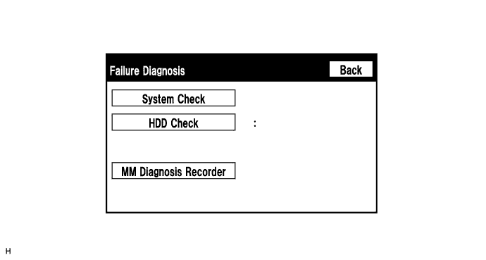
- HINT:
- Each item is grayed out or not displayed based on the device settings.
System Check Mode Screen
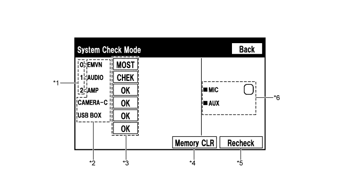
- *1: Node position number for devices connected to the MOST network.
- HINT:
- MOST node position numbers are provided for devices connected to the MOST network.
- *2: Device Name List No. 1
- HINT:
- Device Name List No. 1 displays some of the devices that make up the navigation system.
- The names of the components from Device Name List No. 1 are shown in the following table.
Name
Component
Connection Method
EMVN
Display and navigation module display
-
AUDIO
Radio receiver assembly
Communication line for MOST network
AMP
Stereo component amplifier assembly
Communication line for MOST network
CAMERA-C
Parking assist ECU
Communication line for AVC-LAN
USB BOX
Multi-media interface ECU
Communication line for AVC-LAN
- Device Name List No. 1 displays some of the devices that make up the navigation system.
- *3: Check Result
- HINT:
- Result codes for all devices are displayed.
- When "MOST" is displayed for the result, press "MODE" on the steering pad switch assembly to display the "MOST Line Check" screen.
- Result codes for all devices are displayed.
Result
Meaning
Action
OK
The device does not respond with a DTC.
-
MOST
MOST communication error
Perform "MOST Line Check" to check the connection of each device on the MOST network.
EXCH
The device responds with a "replace"-type DTC.
Look up the DTC in "Unit Check Mode" and replace the device.
CHEK
The device responds with a "check"-type DTC.
Look up the DTC in "Unit Check Mode".
NCON
The device was previously present, but does not respond in diagnostic mode.
- Check power supply wire harness of the device.
- Check the AVC-LAN or MOST network for the device.
NRES
The device responds in diagnostic mode, but gives no DTC information.
- Check power supply wire harness of the device.
- Check the AVC-LAN or MOST network for the device.
- *4: Memory Clear
- HINT:
- Present and history DTCs and registered connected device names are cleared.
- Press the "Memory CLR" switch for 3 seconds.
- Present and history DTCs and registered connected device names are cleared.
- *5: Recheck
- HINT:
- A system check will be performed again after the memory is cleared.
- The "Recheck" switch will dim during a system check.
- A system check will be performed again after the memory is cleared.
- *6: Device Name List No. 2
- HINT:
- Device Name List No. 2 displays some of the devices that make up the navigation system.
- The names of the components from Device Name List No. 2 are shown in the following table.
Name
Component
Connection Method
MIC
Telephone microphone assembly
Vehicle wire harness
AUX
Stereo jack adapter assembly
Vehicle wire harness
- Device Name List No. 2 displays some of the devices that make up the navigation system.
- *1: Node position number for devices connected to the MOST network.
Unit Check Mode Screen
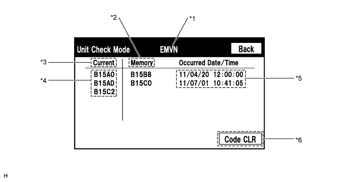
Screen Description Display
Content
*1: Device name
Target device
*2: History DTC
Diagnostic memory results and stored DTCs are displayed.
*3: Present DTC
DTCs output in the service check are displayed.
*4: DTC
DTC (Diagnostic Trouble Code)
*5: Timestamp
The time and date of history DTCs are displayed. (The year is displayed in 2-digit format.)
*6: Diagnosis clear switch
Pushing this switch for 3 seconds clears the diagnostic memory data of the target device. (Both response to diagnostic system check result and the displayed data are cleared.)
MOST Line Check Screen
- HINT:
- The inspection will be performed at the time the screen changes from "System Check Mode" to "MOST Line Check".
- The master unit checks the connection of each device on the MOST network.
- The inspection will be performed at the time the screen changes from "System Check Mode" to "MOST Line Check".
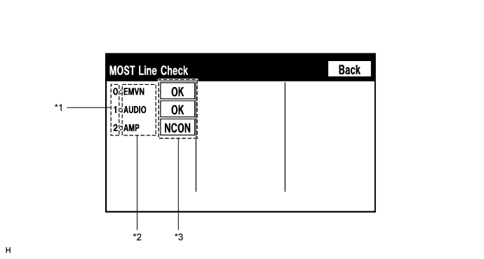
- *1: Node position number for devices connected to the MOST network.
- *2: Device Name List
- HINT:
- Device Name List displays some of the devices that make up the navigation system.
- The names of the components from Device Name List are shown in the following table.
Name
Component
EMVN
Display and navigation module display
AUDIO
Radio receiver assembly
AMP
Stereo component amplifier assembly
- Device Name List displays some of the devices that make up the navigation system.
- *3: Check Result
- HINT:
- The master unit displays the check result on the screen based on the response information from each slave unit.
- Result codes for all devices are displayed.
Result
Meaning
OK
There was a response for the connection check during the MOST line check.
NCON
There was no response for the connection check during the MOST line check.
- The device name and result will not be displayed if there is no system registration record and no response for the connection check during the MOST line check even if the device is connected to the MOST network.
- The master unit displays the check result on the screen based on the response information from each slave unit.
Function Check/Setting Screen
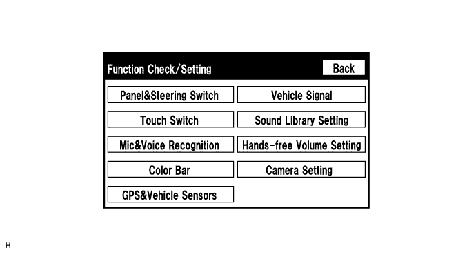
- HINT:
- Each item is grayed out or not displayed based on the device settings.
Microphone & Voice Recognition Check Screen
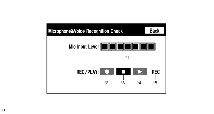
Screen Description Display
Content
*1: Microphone input level meter
Monitors the microphone input level every 0.1 sec. and displays the results in 8 different levels.
*2: Recording switch
Starts recording.
*3: Stop switch
Stops recording and playing.
*4: Play switch
Plays the recorded voice.
*5: Recording indicator
Comes on while recording.
- HINT:
- The microphone is active at all times when this screen is displayed.
- While recording or playing, the switches other than the stop switch cannot be pushed.
- When no recording is present, the play switch cannot be pushed.
- Recording will stop after 5 seconds or when the stop switch is pushed.
- The microphone is active at all times when this screen is displayed.
GPS Information Screen
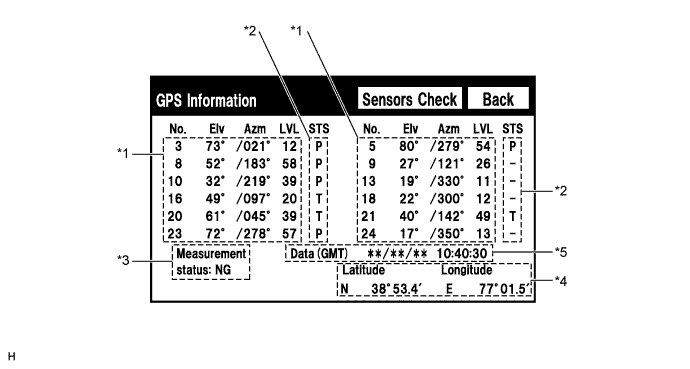
- *1: Satellite information
- HINT:
- Information from a maximum of 12 satellites is displayed on the screen. This information includes the target GPS satellite number, elevation angle, direction and signal level.
- *2: Receiving condition
Screen Description Display
Content
T
The system is receiving a GPS signal, but is not using it for location.
P
The system is using the GPS signal for location.
-
The system cannot receive a GPS signal.
- *3: Measurement information
Screen Description Display
Content
2D
2-dimensional location method is being used.
3D
3-dimensional location method is being used.
NG
Location data cannot be used.
Error
Reception error has occurred.
-
Any other state.
- *4: Position information
Screen Description Display
Content
Position
Latitude and longitude information on the current position is displayed.
- *5: Date information
Screen Description Display
Content
Date
The date/time information obtained from GPS signal is displayed in Greenwich Mean Time (GMT). The last 4 digits are displayed.
- *1: Satellite information
Vehicle Sensors Screen
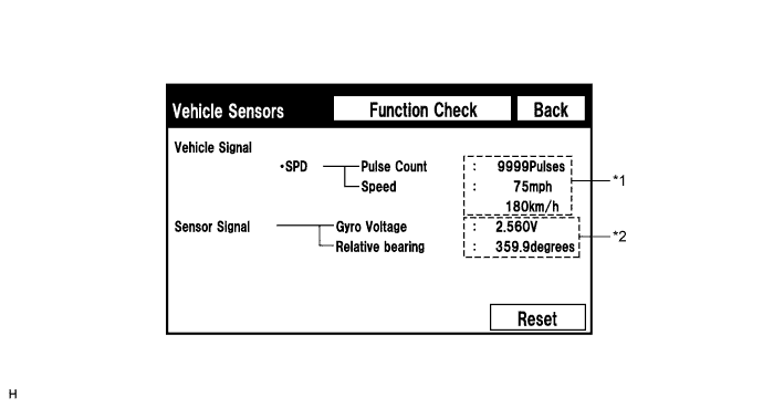
Vehicle Signal Display
Content
*1: SPD
SPD signal condition is displayed.
Sensor Signal Display
Content
*2: Gyro sensor
Gyro sensor output condition is displayed.
2.1 to 2.9 V
- HINT:
- Signals are updated once per second only when vehicle sensor signals are changed.
Vehicle Signal Check Mode Screen
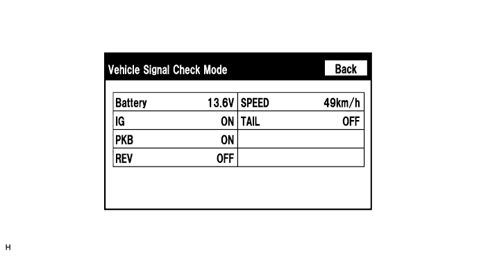
Screen Description Display
Content
Battery
Battery voltage is displayed.
IG
Engine switch ON/OFF state is displayed.
PKB
Parking brake ON/OFF state is displayed.
REV
Reverse signal ON/OFF state is displayed.
SPEED
Vehicle speed is displayed in km/h.
TAIL
TAIL signal (Light control switch) ON/OFF state is displayed.
- HINT:
- Only items sending vehicle signals will be displayed.
- This screen is updated once per second when input signals to the vehicle are changed.
- Only items sending vehicle signals will be displayed.