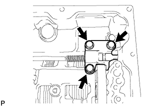
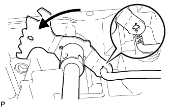
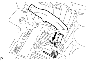
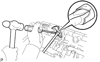
Removal / installation · Vehicles built Sep 2011 – Dec 2011
Versions by build date: Sep 2011 – Dec 2011from Jan 2012
1.
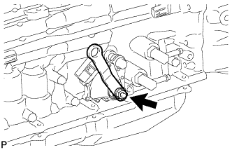
REMOVE TRANSMISSION CONTROL SHAFT LEVER RH
Remove the nut, spring washer and control shaft lever.
2.
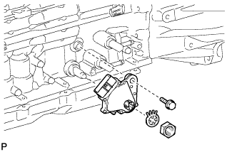
REMOVE PARK/NEUTRAL POSITION SWITCH ASSEMBLY
Using a screwdriver, bend the tabs of the lock washer.
Remove the nut, lock washer and bolt.
Remove the park/neutral position switch.
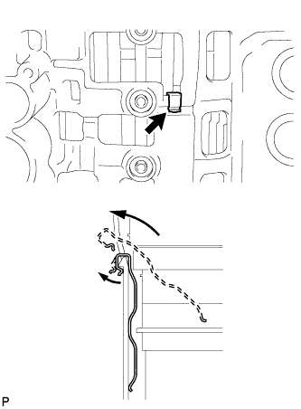
HINT:
Make sure that the manual valve lever shaft has not been rotated prior to installing the park/neutral position switch as the detent spring may become detached from the manual valve lever shaft.
3.
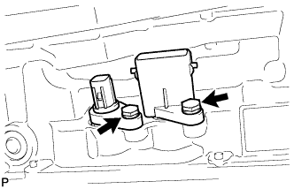
REMOVE SPEED SENSOR
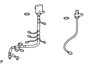
Remove the 2 bolts and 2 speed sensors.
Remove the 2 O-rings from the sensors.
4.
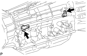
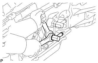
REMOVE OIL COOLER TUBE UNION
Remove the 2 oil cooler tube unions.
Remove the 2 O-rings from the oil cooler tube unions.
5.
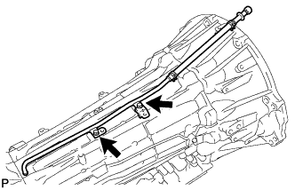
REMOVE AUTOMATIC TRANSMISSION BREATHER TUBE
Remove the 2 bolts.
Remove the breather tube.
Remove the O-ring from the tube.
6.
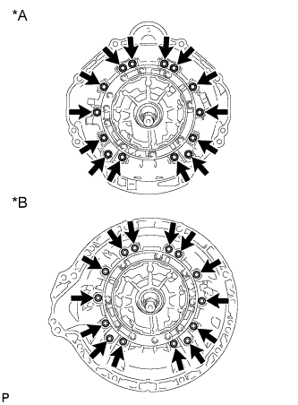
REMOVE AUTOMATIC TRANSMISSION HOUSING
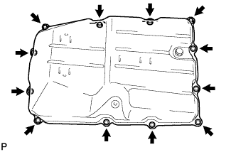
Remove the 14 bolts.
Text in Illustration
*A
for 1VD-FTV
*B
for 3UR-FE
Remove the transmission housing.
7.
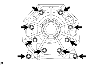
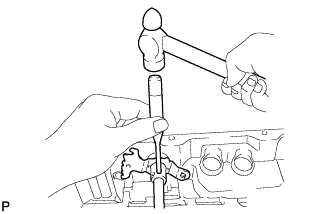
REMOVE REAR TRANSFER ADAPTER
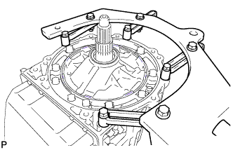
Remove the 10 bolts.
Remove the rear transfer adapter.
HINT:
Tap on the circumference of the extension housing with a plastic-faced hammer to remove the rear transfer adapter.
8.
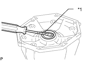
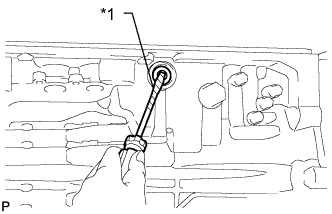
REMOVE TRANSMISSION CASE ADAPTER OIL SEAL
Using a screwdriver, pry out the oil seal.
Text in Illustration
*1
Protective Tape
NOTICE:
Be careful not to damage the rear transfer adapter.
HINT:
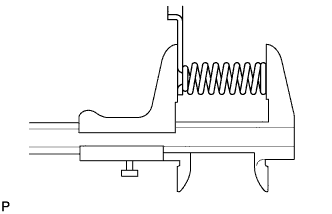
Wrap the tip of the screwdriver with tape.
9.
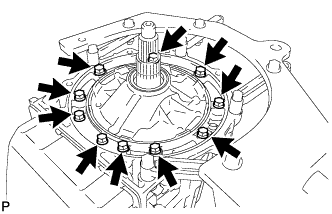
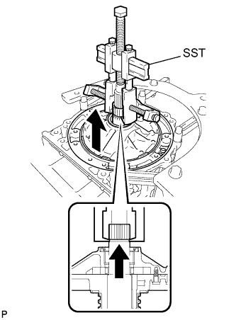
REMOVE TRANSFER CASE ADAPTER RADIAL BALL BEARING
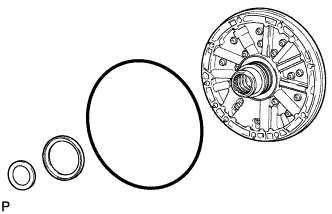
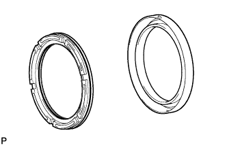
Remove the O-ring and 2 thrust bearing races from the oil pump.
29.
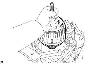
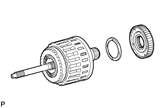
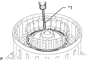
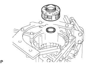
REMOVE CLUTCH DRUM AND INPUT SHAFT ASSEMBLY
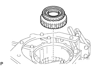
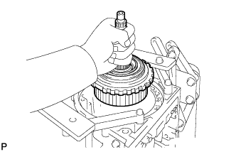
Remove the clutch drum and input shaft assembly from the transmission case.
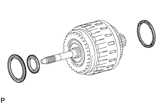
Remove the clutch drum thrust washer and 2 thrust needle roller bearings.
30.
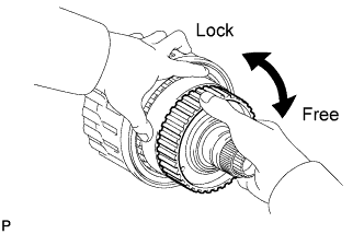
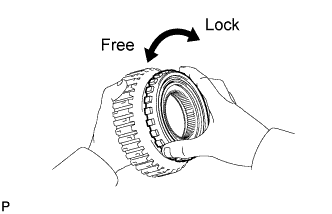
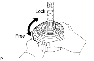
INSPECT NO. 2 1-WAY CLUTCH ASSEMBLY
Hold the reverse clutch hub and turn the 1-way clutch assembly. Check that the 1-way clutch turns freely clockwise and locks when turned counterclockwise.
31.
REMOVE NO. 2 1-WAY CLUTCH ASSEMBLY
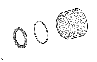
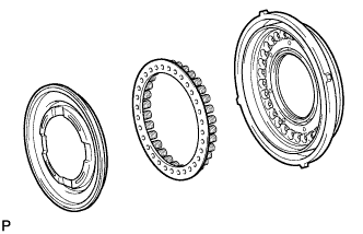
Remove the No. 2 1-way clutch and clutch drum thrust washer from the clutch drum and input shaft assembly.
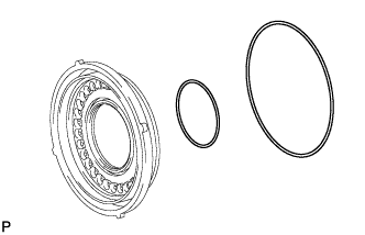
32.
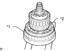
SECURE CLUTCH DRUM AND INPUT SHAFT ASSEMBLY
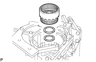
Place the oil pump onto the torque converter, and then place the clutch drum and input shaft assembly onto the oil pump.
Text in Illustration
*1
Torque Converter
*2
Oil Pump
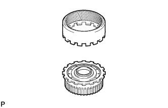
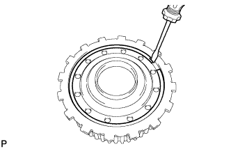
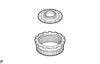
33.
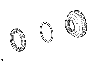
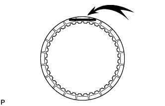
REMOVE REVERSE CLUTCH HUB SUB-ASSEMBLY
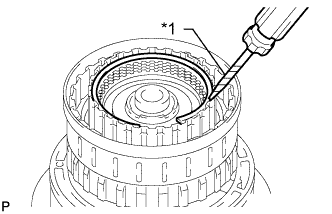
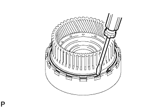
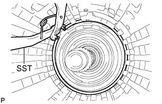
Using a screwdriver, remove the snap ring.
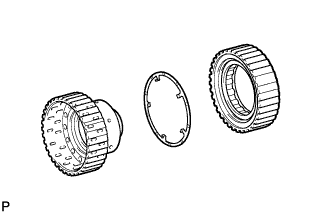
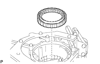
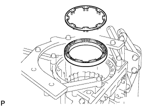
Remove the reverse clutch reaction sleeve and reverse clutch hub sub-assembly together with the rear clutch disc set from the clutch drum.
34.
REMOVE REAR CLUTCH DISC SET
for 1VD-FTV: Remove the cushion plate, reverse clutch flange, 4 discs and 3 plates from the reverse clutch hub.
for 3UR-FE: Remove the cushion plate, reverse clutch flange, 5 discs and 4 plates from the reverse clutch hub.
Remove the flange from the clutch drum.
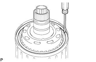
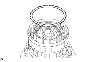
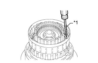
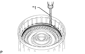
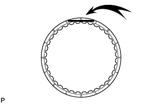
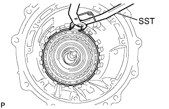
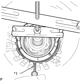
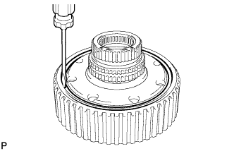
Using a screwdriver, remove the snap ring.
Text in Illustration
*1
Protective Tape
NOTICE:
Be careful not to damage the clutch drum.
HINT:
Wrap the tip of the screwdriver with tape.
35.
INSPECT REAR CLUTCH DISC
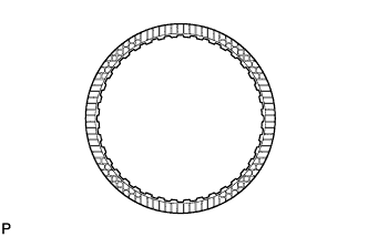
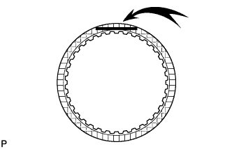
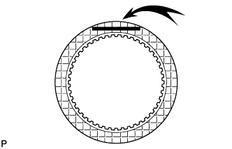
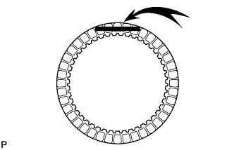
Replace all discs if one of the following problems is present: 1) a disc, plate or flange is worn or burnt, 2) the lining of a disc is peeled off or discolored, or 3) grooves have even a little bit of damage.
NOTICE:
Before assembling new discs, soak them in ATF for at least 2 hours.
36.
INSPECT REVERSE CLUTCH HUB SUB-ASSEMBLY
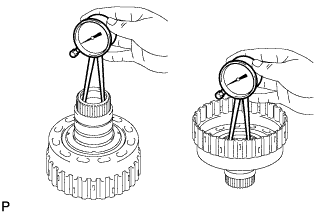
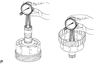
Using a dial indicator, measure the inside diameter of the reverse clutch hub bush.
Standard inside diameter:
41.912 to 41.937 mm (1.410 to 1.411 in.)
If the inside diameter is more than the standard, replace the reverse clutch hub.
37.
REMOVE FORWARD CLUTCH HUB SUB-ASSEMBLY
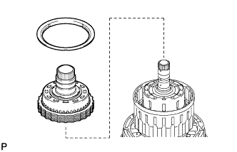
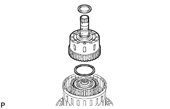
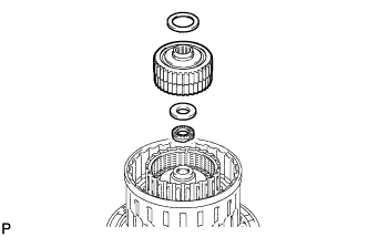
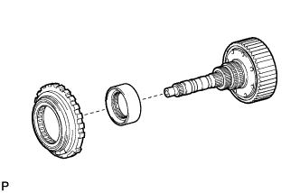
Remove the thrust needle roller bearing, forward clutch hub and No. 3 clutch hub thrust washer from the clutch drum.
38.
INSPECT FORWARD CLUTCH HUB SUB-ASSEMBLY
Using a dial indicator, measure the inside diameter of the forward clutch hub bush.
Standard inside diameter:
30.200 to 30.225 mm (1.189 to 1.190 in.)
If the inside diameter is more than the standard, replace the forward clutch hub.
Remove the 2 thrust needle roller bearings, the coast clutch hub with the No. 4 1-way clutch assembly, and the thrust bearing race from the clutch drum.
40.
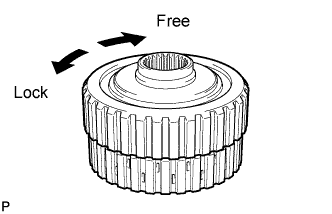
INSPECT NO. 4 1-WAY CLUTCH ASSEMBLY
Hold the coast clutch hub and turn the 1-way clutch assembly. Check that the 1-way clutch turns freely clockwise and locks when turned counterclockwise.
41.
REMOVE NO. 4 1-WAY CLUTCH ASSEMBLY
Separate the No. 4 1-way clutch assembly from the coast clutch hub.
Remove the No. 2 clutch hub thrust washer from the coast clutch hub.
42.
REMOVE FORWARD MULTIPLE DISC CLUTCH DISC SET
Using a screwdriver, remove the snap ring.
Text in Illustration
*1
Protective Tape
NOTICE:
Be careful not to damage the forward clutch piston.
HINT:
Wrap the tip of the screwdriver with tape.
Remove the flange, 6 discs, 6 plates and cushion plate from the input shaft.
43.
INSPECT FORWARD MULTIPLE DISC CLUTCH DISC
Replace all discs if one of the following problems is present: 1) a disc, plate or flange is worn or burnt, 2) the lining of a disc is peeled off or discolored, or 3) grooves or printed numbers have even a little bit of damage.
NOTICE:
Before assembling new discs, soak them in ATF for at least 2 hours.
44.
REMOVE COAST CLUTCH DISC SET
Using a screwdriver, remove the snap ring.
Text in Illustration
*1
Protective Tape
NOTICE:
Be careful not to damage the forward clutch piston.
HINT:
Wrap the tip of the screwdriver with tape.
for 1VD-FTV: Remove the coast clutch flange, 5 discs and 5 plates from the input shaft.
for 3UR-FE: Remove the coast clutch flange, 4 discs and 4 plates from the input shaft.
45.
INSPECT COAST CLUTCH DISC
Replace all discs if one of the following problems is present: 1) a disc, plate or flange is worn or burnt, 2) the lining of a disc is peeled off or discolored, or 3) grooves or printed numbers have even a little bit of damage.
NOTICE:
Before assembling new discs, soak them in ATF for at least 2 hours.
46.
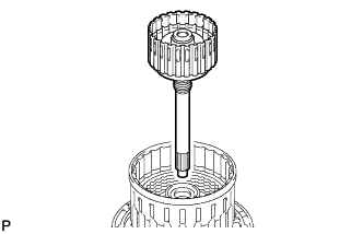
REMOVE INPUT SHAFT SUB-ASSEMBLY
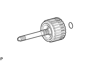
Remove the input shaft from the clutch drum.
47.
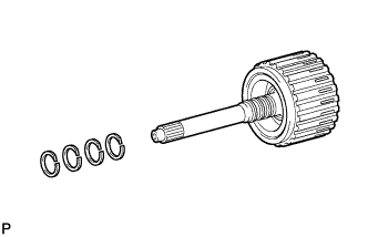
REMOVE INPUT SHAFT OIL SEAL RING
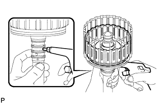
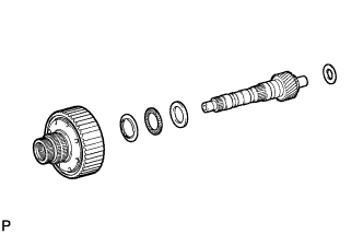
Remove the 4 oil seal rings from the input shaft.
48.
REMOVE COAST CLUTCH PISTON
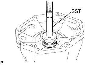
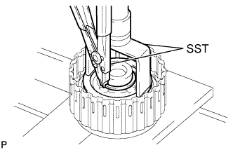
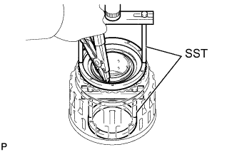
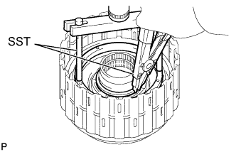
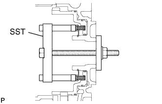
Place SST on the No. 1 clutch balancer and compress the forward clutch return spring with a press.
SST
09350-30020
(09350-07040)
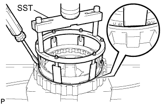
Using SST, remove the snap ring.
SST
09350-30020
(09350-07070)
Remove the No. 1 clutch balancer and forward clutch return spring from the input shaft.
Remove the O-ring from the No. 1 clutch balancer.
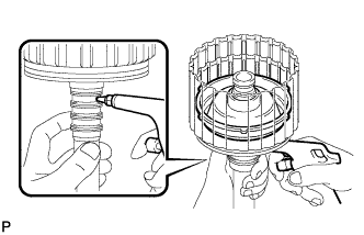
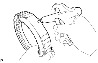
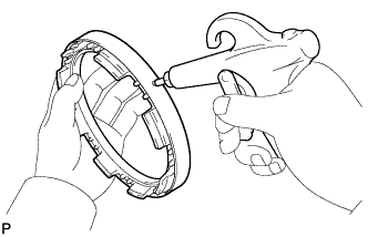
Hold the input shaft by hand and apply compressed air to the input shaft to remove the coast clutch piston.
49.
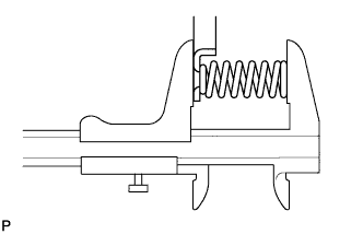
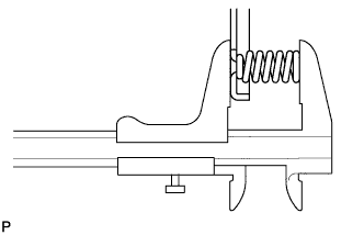
INSPECT FORWARD CLUTCH RETURN SPRING SUB-ASSEMBLY
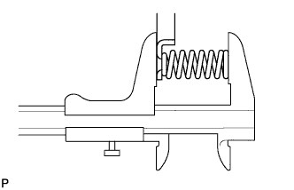
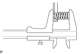
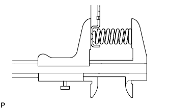
Using a vernier caliper, measure the free length of the spring together with the spring seat.
Standard free length:
29.65 mm (1.17 in.)
50.
REMOVE FORWARD CLUTCH PISTON SUB-ASSEMBLY
Hold the input shaft by hand and apply compressed air to the input shaft to remove the forward clutch piston.
Remove the O-ring from the input shaft.
51.
REMOVE NO. 3 CLUTCH BALANCER
Place SST on the No. 3 clutch balancer and compress the reverse clutch return spring with a press.
Remove the reverse clutch return spring and O-ring from the reverse clutch piston.
52.
INSPECT REVERSE CLUTCH RETURN SPRING SUB-ASSEMBLY
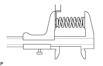
Using a vernier caliper, measure the free length of the spring together with the spring seat.
Standard free length:
21.24 mm (0.836 in.)
53.
REMOVE REVERSE CLUTCH PISTON SUB-ASSEMBLY
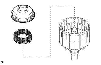
Remove the reverse clutch piston from the clutch drum.
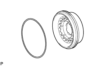
Remove the O-ring from the reverse clutch piston.
Remove the O-ring from the clutch drum.
54.
REMOVE DIRECT CLUTCH DISC SET
Using a screwdriver, remove the snap rings from the clutch drum.
Text in Illustration
*1
Protective Tape
NOTICE:
Be careful not to damage the clutch drum.
HINT:
Wrap the tip of the screwdriver with tape.
for 1VD-FTV: Remove the direct clutch flange, 6 discs and 6 plates from the clutch drum.
for 3UR-FE: Remove the direct clutch flange, 5 discs and 5 plates from the clutch drum.
55.
INSPECT DIRECT CLUTCH DISC
Replace all discs if one of the following problems is present: 1) a disc, plate or flange is worn or burnt, 2) the lining of a disc is peeled off or discolored, or 3) grooves or printed numbers have even a little bit of damage.
NOTICE:
Before assembling new discs, soak them in ATF for at least 2 hours.
56.
REMOVE DIRECT CLUTCH PISTON SUB-ASSEMBLY
Place SST on the direct clutch piston and compress the direct clutch return spring with a press.
Place the oil pump onto the torque converter, and then place the clutch drum onto the oil pump.
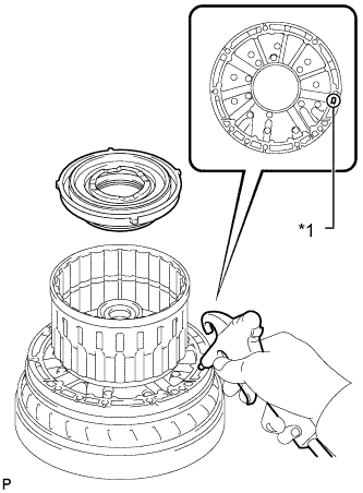
Hold the direct clutch piston by hand and apply compressed air to the oil hole of the oil pump as shown in the illustration to remove the direct clutch piston together with the No. 2 clutch balancer and direct clutch return spring sub-assembly.
Text in Illustration
*1
Oil Hole
Remove the No. 2 clutch balancer and direct clutch return spring sub-assembly from the direct clutch piston.
Remove the 2 O-rings from the direct clutch piston.
57.
INSPECT DIRECT CLUTCH RETURN SPRING SUB-ASSEMBLY
Using a vernier caliper, measure the free length of the spring together with the spring seat.
Standard free length:
19.46 mm (0.766 in.)
58.
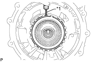
REMOVE NO. 3 BRAKE SNAP RING
Using a screwdriver, remove the No. 3 brake snap ring from the transmission case.
Text in Illustration
*1
Protective Tape
NOTICE:
Be careful not to damage the transmission case.
HINT:
Wrap the tip of the screwdriver with tape.
59.
REMOVE NO. 3 BRAKE DISC SET
Remove the 2 flanges, 4 discs and 3 plates from the transmission case.
60.
INSPECT NO. 3 BRAKE DISC
Replace all discs if one of the following problems is present: 1) a disc, plate or flange is worn or burnt, 2) the lining of a disc is peeled off or discolored, or 3) grooves or printed numbers have even a little bit of damage.
NOTICE:
Before assembling new discs, soak them in ATF for at least 2 hours.
61.
REMOVE NO. 3 BRAKE PISTON HOLE SNAP RING
Using SST, remove the snap ring.
SST
09350-30020
(09350-07060)
62.
REMOVE NO. 3 BRAKE CYLINDER WITH NO. 3 BRAKE PISTON AND NO. 3 BRAKE PISTON RETURN SPRING SUB-ASSEMBLY
Remove the No. 3 brake cylinder with the No. 3 brake piston and No. 3 brake piston return spring from the transmission case.
63.
REMOVE NO. 3 BRAKE PISTON
Using SST and a press, compress the No. 3 brake piston return spring and remove the snap ring and No. 3 brake piston return spring with a screwdriver.
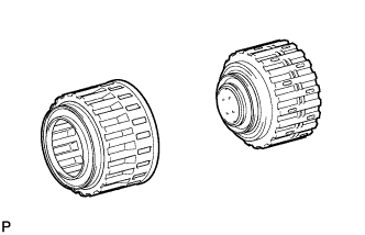
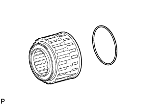
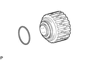
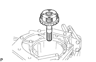
Remove the 1-way clutch assembly with 1-way clutch inner race from the transmission case.
66.
INSPECT 1-WAY CLUTCH ASSEMBLY
Install the 1-way clutch to the 1-way clutch inner race.
Hold the 1-way clutch inner race and turn the 1-way clutch. Check that the 1-way clutch turns freely counterclockwise and locks when turned clockwise.
Remove the 1-way clutch from the 1-way clutch inner race.
67.
REMOVE 1-WAY CLUTCH INNER RACE SUB-ASSEMBLY
Separate the 1-way clutch inner race from the 1-way clutch assembly and remove the No. 1 planetary carrier thrust washer.
68.
REMOVE FRONT PLANETARY GEAR ASSEMBLY
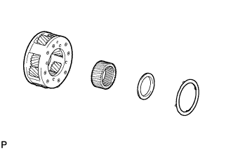
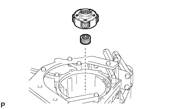
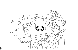
Remove the front planetary gear assembly and thrust needle roller bearing from the transmission case.
Remove the No. 2 planetary carrier thrust washer, thrust bearing race and front planetary sun gear from the front planetary gear assembly.
69.
INSPECT FRONT PLANETARY GEAR ASSEMBLY
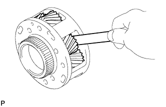
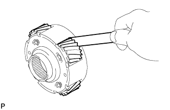
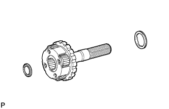
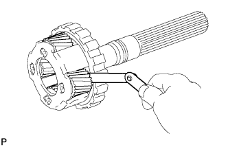
Using a feeler gauge, measure the front planetary pinion gear thrust clearance.
Standard clearance:
0.2 to 0.6 mm (0.00787 to 0.0236 in.)
If the clearance is more than the standard, replace the front planetary gear assembly.
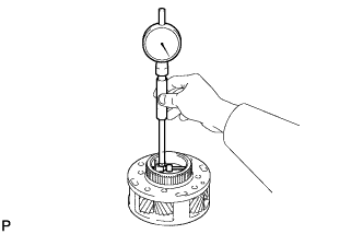
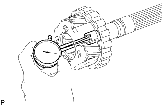
Using a cylinder gauge, measure the inside diameter of the front planetary gear bush.
Standard inside diameter:
61.005 to 61.030 mm (2.402 to 2.403 in.)
If the inside diameter is more than the standard, replace the front planetary gear.
70.
REMOVE FRONT PLANETARY RING GEAR WITH FRONT PLANETARY RING GEAR FLANGE SUB-ASSEMBLY AND CENTER PLANETARY RING GEAR
Remove the front planetary ring gear together with the front planetary ring gear flange and center planetary ring gear from the transmission case.
Remove the thrust needle roller bearing and thrust bearing race.
71.
REMOVE FRONT PLANETARY RING GEAR
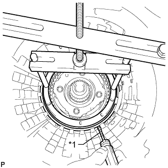
Using a screwdriver, remove the snap ring.
Remove the front planetary ring gear from the center planetary ring gear.
72.
REMOVE CENTER PLANETARY RING GEAR
Using a screwdriver, remove the snap ring.
Remove the center planetary ring gear from the front planetary ring gear flange.
73.
REMOVE NO. 1 BRAKE DISC SET
Remove the flange, 4 discs and 4 plates from the transmission case.
74.
INSPECT NO. 1 BRAKE DISC
Replace all discs if one of the following problems is present: 1) a disc, plate or flange is worn or burnt, 2) the lining of a disc is peeled off or discolored, or 3) grooves or printed numbers have even a little bit of damage.
NOTICE:
Before assembling new discs, soak them in ATF for at least 2 hours.
Using a screwdriver, remove the snap ring from the transmission case.
Text in Illustration
*1
Protective Tape
NOTICE:
Be careful not to damage the transmission case.
HINT:
Wrap the tip of the screwdriver with tape.
Remove the No. 2 brake flange, flange, 4 discs, 3 plates and No. 2 brake piston return spring from the transmission case.
81.
INSPECT NO. 2 BRAKE DISC
Replace all discs if one of the following problems is present: 1) a disc, plate or flange is worn or burnt, 2) the lining of a disc is peeled off or discolored, or 3) grooves or printed numbers have even a little bit of damage.
NOTICE:
Before assembling new discs, soak them in ATF for at least 2 hours.
82.
INSPECT NO. 2 BRAKE PISTON RETURN SPRING SUB-ASSEMBLY
Using a vernier caliper, measure the free length of the spring together with the spring seat.
Remove the No. 2 brake cylinder together with the No. 2 brake piston from the transmission case.
84.
REMOVE NO. 2 BRAKE PISTON
Hold the No. 2 brake piston and apply compressed air to the No. 2 brake cylinder to remove the No. 2 brake piston.
HINT:
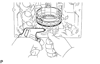
If the piston does not pop out with compressed air, lift the piston out with needle-nose pliers.
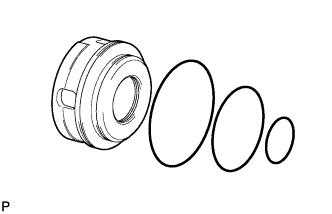
Remove the 2 O-rings from the No. 2 brake piston.
85.
REMOVE INTERMEDIATE SHAFT WITH NO. 3 1-WAY CLUTCH ASSEMBLY, REAR PLANETARY RING GEAR FLANGE AND REAR PLANETARY RING GEAR
Using SST, remove the snap ring from the transmission case.
SST
09350-30020
(09350-07060)
Remove the intermediate shaft with No. 3 1-way clutch assembly, rear planetary ring gear flange and rear planetary ring gear from the transmission case.
86.
INSPECT NO. 3 1-WAY CLUTCH ASSEMBLY
Hold the rear planetary ring gear flange and turn the 1-way clutch. Check that the 1-way clutch turns freely counterclockwise and locks when turned clockwise.
87.
REMOVE 1-WAY CLUTCH INNER RACE
Remove the No. 3 1-way clutch assembly and 1-way clutch inner race from the intermediate shaft.
88.
REMOVE REAR PLANETARY RING GEAR
Remove the rear planetary ring gear with rear planetary ring gear flange, 3 thrust bearing races and thrust needle roller bearing from the intermediate shaft.
Using a screwdriver, remove the snap ring.
Remove the rear planetary ring gear flange from the rear planetary ring gear.
89.
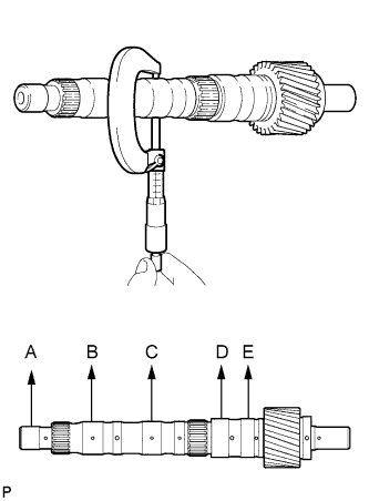
INSPECT INTERMEDIATE SHAFT
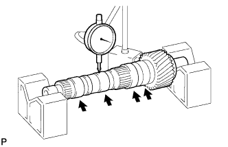
Using a dial indicator, check the intermediate shaft runout.
Standard runout:
0.03 mm (0.00118 in.)
If the runout is more than the standard, replace the intermediate shaft with a new one.
Using a micrometer, check the diameter of the intermediate shaft at the positions shown in the diagram.
Standard diameter:
A:
19.963 to 19.976 mm (0.7859 to 0.7865 in.)
B, C:
30.150 to 30.163 mm (1.187 to 1.188 in.)
D, E:
36.404 to 36.420 mm (1.433 to 1.434 in.)
If the diameter is less than the standard, replace the intermediate shaft with a new one.
90.
REMOVE NO. 4 BRAKE DISC SET
Remove the No. 4 brake flange, flange, 7 No. 4 brake discs and 6 plates from the transmission case.
91.
INSPECT NO. 4 BRAKE DISC
Replace all discs if one of the following problems is present: 1) a disc, plate or flange is worn or burnt, 2) the lining of a disc is peeled off or discolored, or 3) grooves or printed numbers have even a little bit of damage.
NOTICE:
Before assembling new discs, soak them in ATF for at least 2 hours.
92.
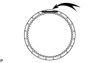
REMOVE BRAKE PLATE STOPPER SPRING
NOTICE:
When removing the brake plate stopper spring, do not apply excessive force and do not deform it.
93.
REMOVE REAR PLANETARY GEAR ASSEMBLY
Remove the rear planetary gear assembly from the transmission case.
Remove the 2 thrust needle roller bearings from the rear planetary gear assembly.
Remove the thrust bearing race from the transmission case.
94.
INSPECT REAR PLANETARY GEAR ASSEMBLY
Using a feeler gauge, measure the rear planetary pinion gear thrust clearance.
Standard clearance:
0.2 to 0.6 mm (0.00787 to 0.0236 in.)
If the clearance is more than the standard, replace the planetary gear assembly.
Using a dial indicator, measure the inside diameter of the rear planetary gear bush.
Standard inside diameter:
20.0 to 20.025 mm (0.787 to 0.788 in.)
If the inside diameter is more than the standard, replace the rear planetary gear assembly.
95.
REMOVE 1ST AND REVERSE BRAKE RETURN SPRING SUB-ASSEMBLY
Place SST on the 1st and reverse brake return spring and compress the 1st and reverse brake return spring.
Using SST, remove the snap ring and 1st and reverse brake return spring.
SST
09350-30020
(09350-07070)
Hold the 1st and reverse brake piston and apply compressed air (392 kPa, 4.0 kgf/cm2, 57 psi) to the transmission case to remove the 1st and reverse brake piston.
HINT:
If the piston does not pop out with compressed air, lift the piston out with needle-nose pliers.
Remove the 3 O-rings from the 1st and reverse brake piston.
96.
INSPECT 1ST AND REVERSE BRAKE RETURN SPRING SUB-ASSEMBLY
Using a vernier caliper, measure the free length of the spring together with the spring seat.