Removal / installation · Vehicles built Sep 2011 – Dec 2011
Versions by build date: Sep 2011 – Dec 2011from Jan 2012
NOTICE:
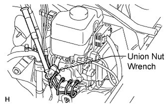
Be sure not to allow the pump to contact the floor; support it with the booster body. If the pump contacts the floor, the red brake tube between the pump and booster body may be deformed, the operating sound of the pump may become loud enough to hear within the cabin, and fluid may leak.
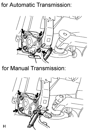
When installing, coat the parts indicated by arrows with lithium soap base glycol grease (Click here).
As high pressure is applied to the brake actuator tube No. 1, never deform it.
Until the work is over, do not turn the ignition switch on.
Before starting the work, make sure that the ignition switch is off and depress the brake pedal more than 20 times.
HINT:
When pressure in the power supply system is released, the reaction force becomes light and the stroke becomes longer.
1.
DRAIN BRAKE FLUID
NOTICE:
Wash off brake fluid immediately if it comes into contact with a painted surface.
2.
DISCONNECT CABLE FROM NEGATIVE BATTERY TERMINAL
NOTICE:
When disconnecting the cable, some systems need to be initialized after the cable is reconnected (Click here).
3.
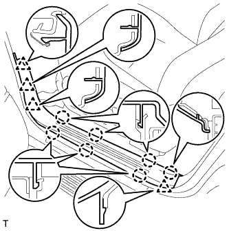
REMOVE FRONT DOOR SCUFF PLATE LH
Detach the 7 claws and 4 clips, and remove the scuff plate.
4.
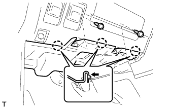
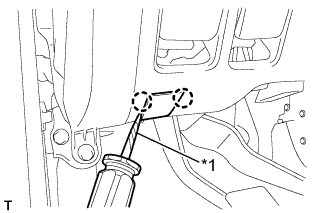
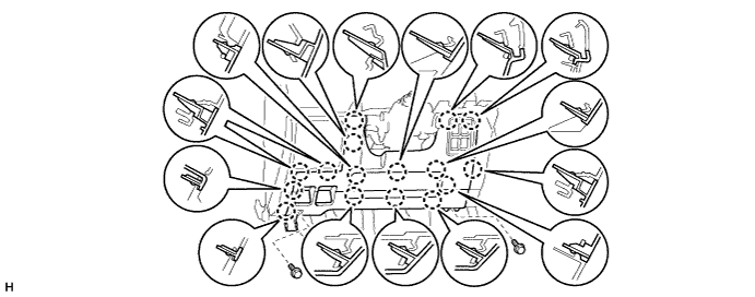
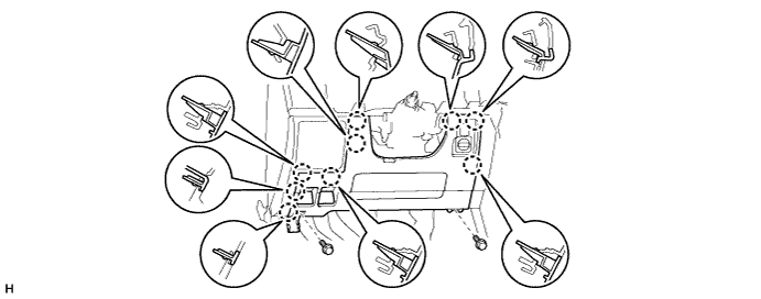
REMOVE NO. 1 INSTRUMENT PANEL UNDER COVER SUB-ASSEMBLY
Remove the 2 screws.
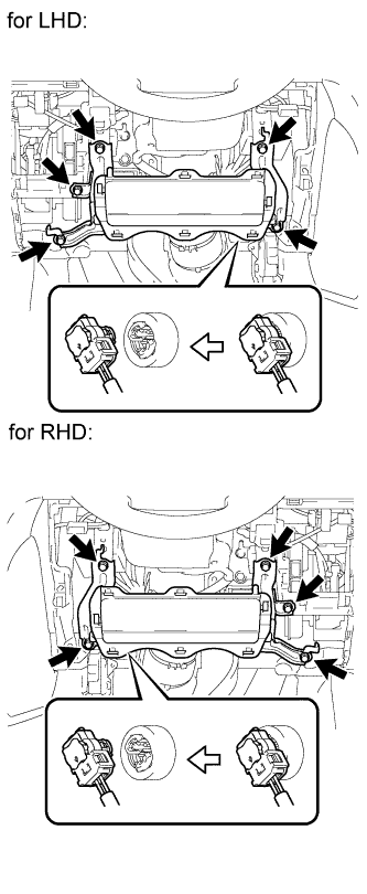
Detach the 3 claws.
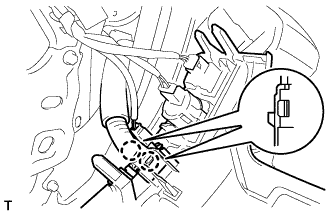
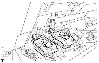
Disconnect the connectors and remove the No. 1 instrument panel under cover.
5.
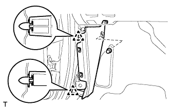
REMOVE COWL SIDE TRIM BOARD LH
Remove the cap nut.
Detach the 2 clips and remove the cowl side trim board.