INSTALLATION
Removal / installation · Vehicles built from Jan 2012
Versions by build date: Sep 2011 – Dec 2011 from Jan 2012
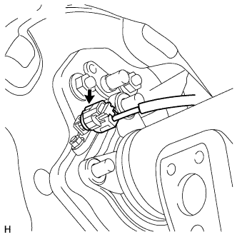
| 1.
INSTALL REAR SPEED SENSOR LH |
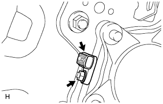
 |
- Install the speed sensor with the nut.
-
Torque:
- 8.3 N*m{
85 kgf*cm
, 73 in.*lbf
}
- NOTICE:
- Make sure there are no pieces of iron or other foreign matter attached to the sensor tip.
- While inserting the speed sensor into the knuckle hole, do not strike or damage the sensor tip.
- After installing the speed sensor, make sure there is no clearance or foreign matter between the sensor stay part and the knuckle.
- Make sure there is no foreign matter attached to the speed sensor rotor.
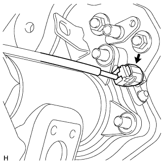
| 2.
INSTALL REAR SPEED SENSOR RH |
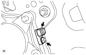
|
- Install the speed sensor with the nut.
-
Torque:
- 8.3 N*m{
85 kgf*cm
, 73 in.*lbf
}
- NOTICE:
- Make sure there are no pieces of iron or other foreign matter attached to the sensor tip.
- While inserting the speed sensor into the knuckle hole, do not strike or damage the sensor tip.
- After installing the speed sensor, make sure there is no clearance or foreign matter between the sensor stay part and the knuckle.
- Make sure there is no foreign matter attached to the speed sensor rotor.
| 3.
INSTALL SKID CONTROL SENSOR WIRE |
|
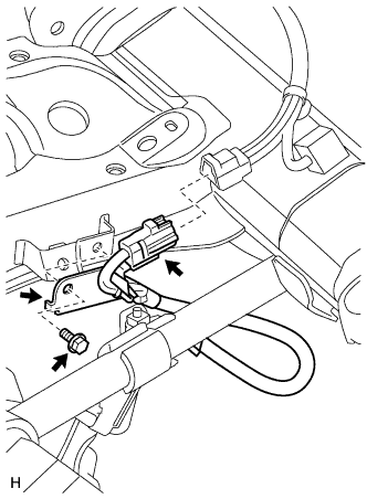
- Install the sensor clamp with the bolt.
-
Torque:
- 13 N*m{
127 kgf*cm
, 9 ft.*lbf
}
- NOTICE:
- Make sure the clamp rotation stopper touches the installation position.
Connect the connector.
- NOTICE:
- Securely insert the connector.
- When connecting the connector, do not twist the wire harness.
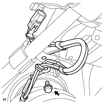
- Install the sensor clamp with the bolt.
-
Torque:
- 13 N*m{
127 kgf*cm
, 9 ft.*lbf
}
- NOTICE:
- Make sure the clamp rotation stopper touches the installation position.
- Connect the speed sensor RH connector.
- NOTICE:
- Securely connect the connector.
- When connecting the connector, do not twist the wire harness.
Attach the 3 clamps.
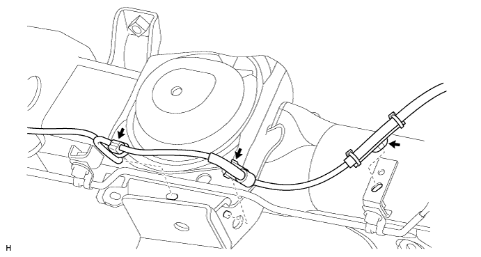

- NOTICE:
- When attaching the clamps, do not twist the wire harness.
- When attaching the clamps, securely insert them as shown in the illustration.
Attach the 5 clamps.
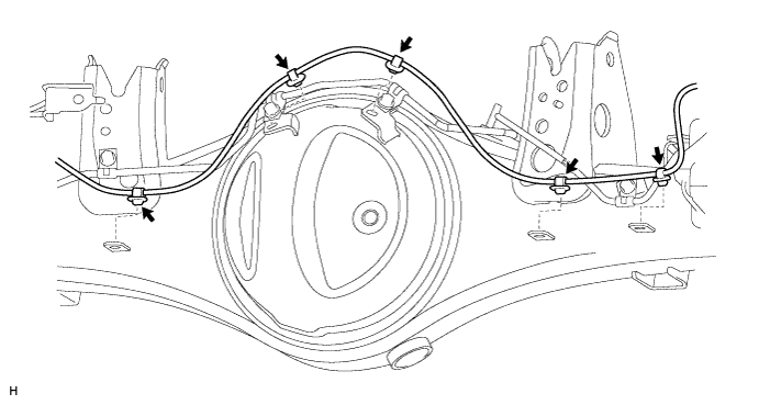
- NOTICE:
- When attaching the clamps, do not twist the wire harness.
- When attaching the clamps, securely insert them as shown in the illustration.
Attach the 2 clamps, and install the sensor clamp with the bolt.
-
Torque:
- 13 N*m{
127 kgf*cm
, 9 ft.*lbf
}
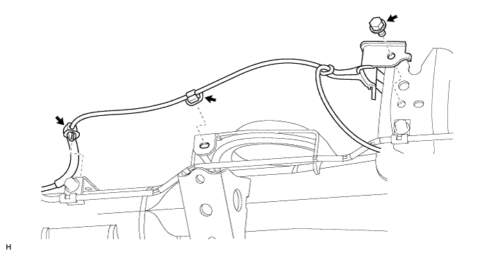
- Connect the speed sensor LH connector.
- NOTICE:
- Securely connect the connector.
- When connecting the connector, do not twist the wire harness.
| 4.
INSTALL REAR WHEEL |
|
-
Torque:
- for Aluminum Wheel:
- 131 N*m{
1336 kgf*cm
, 97 ft.*lbf
}
- for Steel Wheel:
- 209 N*m{
2131 kgf*cm
, 154 ft.*lbf
}
| 5.
CONNECT CABLE TO NEGATIVE BATTERY TERMINAL |
|
- NOTICE:
- When disconnecting the cable, some systems need to be initialized after the cable is reconnected (Click here).
| 6.
CHECK SPEED SENSOR SIGNAL |
|
w/ ABS:
Check the speed sensor signal (Click here).
w/ VSC:
Check the speed sensor signal (Click here).