B2796 No Communication in Immobiliser System
Diagnostic trouble codes · Vehicles built Sep 2011 – Dec 2011
Versions by build date: Sep 2011 – Dec 2011 from Jan 2012
DESCRIPTION
- DTC B2796 is stored when a key is inserted into the ignition key cylinder but no communication occurs between the key and transponder key ECU assembly.
| DTC Code |
DTC Detection Condition |
Trouble Area |
DTC Output Confirmation Operation |
| B2796 |
The key code cannot be transmitted (1 trip detection logic*). |
|
Insert the key into the ignition key cylinder. |
- *: Only output while a malfunction is present.
| Vehicle Condition when Malfunction Detected |
Fail-safe Operation when Malfunction Detected |
| Engine cannot be started |
- |
| DTC Code |
Data List and Active Test |
| B2796 |
Response |
WIRING DIAGRAM
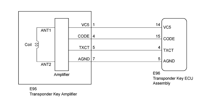

INSPECTION PROCEDURE
- NOTICE:
- When replacing the transponder key ECU assembly or key, refer to the Service Bulletin.
- After performing repairs, perform the operation that fulfills the DTC output confirmation operation, and then confirm that no DTCs are output again.
- When replacing the transponder key ECU assembly or key, refer to the Service Bulletin.
| 1. CLEAR DTC |

Clear the DTCs (Click here).
| NEXT | |
 |
| 2. CHECK FOR DTC |
Insert and remove each registered key one at a time, and check for DTCs each time (Click here).
- HINT:
- Before checking for DTCs, perform the "DTC Output Confirmation Operation" procedure.
- If DTC B2796 is output, check for DTCs with the next key after clearing the DTCs.
- Before checking for DTCs, perform the "DTC Output Confirmation Operation" procedure.
- OK:
- DTC B2796 is not output.
Result Result
Proceed to
OK
A
NG (all keys)
B
NG (any key)
C
|
|
||||
|
|
||||


| A | ||
 |
||
| ||
| 3. CHECK CONNECTION OF CONNECTOR |
Check the connection of the transponder key ECU assembly and transponder key amplifier connectors.
Visually inspect the terminals of the transponder key ECU assembly and transponder key amplifier connectors.
- OK:
- Connectors are properly connected.
|
|
||||
| OK | |
|
| 4. CHECK WHETHER ENGINE STARTS |
Check that the engine starts with an already registered vehicle key.
- OK:
- Engine starts normally.
|
|
||||
| OK | |
|
| 5. CLEAR DTC |
Clear the DTCs (Click here).
| NEXT | |
|
| 6. CHECK FOR DTC |
Check for DTCs (Click here).
- HINT:
- Before checking for DTCs, perform the "DTC Output Confirmation Operation" procedure.
- OK:
- DTC B2796 is not output.
|
|
||||
| OK | ||
|
||
| ||
| 7. CHECK TRANSPONDER KEY AMPLIFIER |
Using an oscilloscope, check the waveform.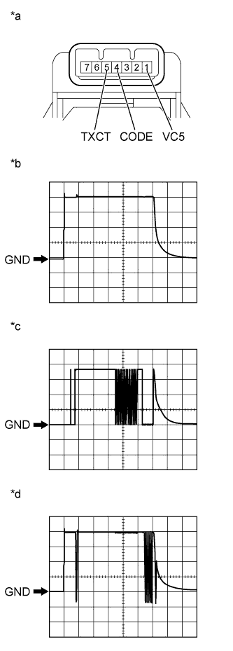
Waveform 1 (Reference)
Measurement Condition Item
Content
Tester Connection
E95-1 (VC5) - Body ground
Tool Setting
1 V/DIV., 20 ms./DIV.
Condition
Key inserted in ignition key cylinder
Waveform 2 (Reference)
Measurement Condition Item
Content
Tester Connection
E95-5 (TXCT) - Body ground
Tool Setting
1 V/DIV., 20 ms./DIV.
Condition
Key inserted in ignition key cylinder
Waveform 3 (Reference)
Measurement Condition Item
Content
Tester Connection
E95-4 (CODE) - Body ground
Tool Setting
1 V/DIV., 20 ms./DIV.
Condition
Key inserted in ignition key cylinder
- OK:
- Waveform is output normally (refer to illustration).
Text in Illustration *a
Component with harness connected
(Transponder Key Amplifier)
*b
Waveform 1
*c
Waveform 2
*d
Waveform 3
Result Result
Proceed to
OK
A
NG (Waveform 1)
B
NG (Waveform 2)
C
NG (Waveform 3)
D
|
|
||||
|
|
||||
|
|
||||
| A | ||
|
||
| ||
| 8. CHECK TRANSPONDER KEY AMPLIFIER (VC5) |
Disconnect the E95 transponder key amplifier connector.
Using an oscilloscope, check the waveform.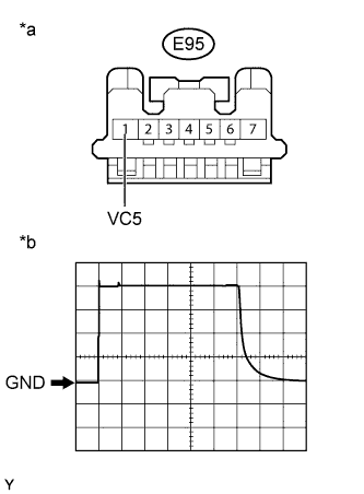
Waveform (Reference)
Measurement Condition Item
Content
Tester Connection
E95-1 (VC5) - Body ground
Tool Setting
1 V/DIV., 20 ms./DIV.
Condition
Key inserted in ignition key cylinder
- OK:
- Waveform is output normally (refer to illustration).
Text in Illustration *a
Front view of wire harness connector
(to Transponder Key Amplifier)
*b
Waveform
|
|
||||
| OK | ||
|
||
| ||
| 9. CHECK HARNESS AND CONNECTOR (TRANSPONDER KEY AMPLIFIER - TRANSPONDER KEY ECU ASSEMBLY) |
Disconnect the E95 transponder key amplifier connector.
Disconnect the E96 transponder key ECU assembly connector.
Measure the resistance according to the value(s) in the table below.
- Standard Resistance:
Tester Connection
Condition
Specified Condition
E95-1 (VC5) - E96-14 (VC5)
Always
Below 1 Ω
E95-7 (AGND) - E96-5 (AGND)
Always
Below 1 Ω
E95-1 (VC5) - Body ground
Always
10 kΩ or higher
|
|
||||
| OK | ||
|
||
| ||
| 10. CHECK TRANSPONDER KEY AMPLIFIER (TXCT) |
Disconnect the E95 transponder key amplifier connector.
Using an oscilloscope, check the waveform.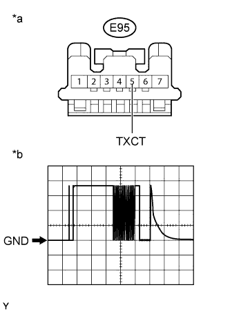
Waveform (Reference)
Measurement Condition Item
Content
Tester Connection
E95-5 (TXCT) - Body ground
Tool Setting
1 V/DIV., 20 ms./DIV.
Condition
Key inserted in ignition key cylinder
- OK:
- Waveform is output normally (refer to illustration).
Text in Illustration *a
Front view of wire harness connector
(to Transponder Key Amplifier)
*b
Waveform
|
|
||||
| OK | ||
|
||
| ||
| 11. CHECK HARNESS AND CONNECTOR (TRANSPONDER KEY AMPLIFIER - TRANSPONDER KEY ECU ASSEMBLY) |
Disconnect the E95 transponder key amplifier connector.
Disconnect the E96 transponder key ECU assembly connector.
Measure the resistance according to the value(s) in the table below.
- Standard Resistance:
Tester Connection
Condition
Specified Condition
E95-5 (TXCT) - E96-4 (TXCT)
Always
Below 1 Ω
E95-5 (TXCT) - Body ground
Always
10 kΩ or higher
|
|
||||
| OK | ||
|
||
| ||
| 12. CHECK TRANSPONDER KEY AMPLIFIER (CODE) |
Disconnect the E95 transponder key amplifier connector.
Using an oscilloscope, check the waveform.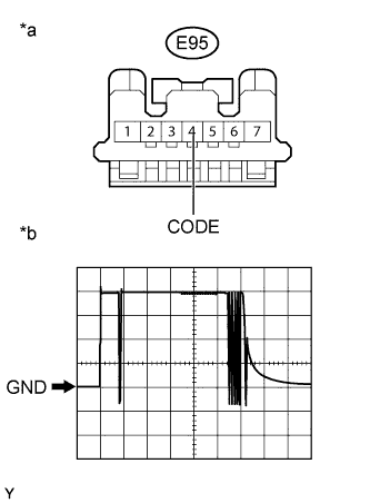
Waveform (Reference)
Measurement Condition Item
Content
Tester Connection
E95-4 (CODE) - Body ground
Tool Setting
1 V/DIV., 20 ms./DIV.
Condition
Key inserted in ignition key cylinder
- OK:
- Waveform is output normally (refer to illustration).
Text in Illustration *a
Front view of wire harness connector
(to Transponder Key Amplifier)
*b
Waveform
|
|
||||
| OK | ||
|
||
| ||
| 13. CHECK HARNESS AND CONNECTOR (TRANSPONDER KEY AMPLIFIER - TRANSPONDER KEY ECU ASSEMBLY) |
Disconnect the E95 transponder key amplifier connector.
Disconnect the E96 transponder key ECU assembly connector.
Measure the resistance according to the value(s) in the table below.
- Standard Resistance:
Tester Connection
Condition
Specified Condition
E95-4 (CODE) - E96-15 (CODE)
Always
Below 1 Ω
E95-4 (CODE) - Body ground
Always
10 kΩ or higher
|
|
||||
| OK | ||
|
||
| ||