REMOVAL
Removal / installation · Vehicles built from Sep 2011
- HINT:
- Use the same procedures for the LH side and RH side.
- The procedures listed below are for the LH side.
- Use the same procedures for the LH side and RH side.
| 1. REMOVE STABILIZER CONTROL VALVE PROTECTOR (w/ KDSS) |

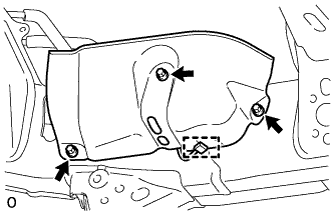  |
Detach the clamp, and disconnect the connector from the protector.
Remove the 3 bolts and protector.
| 2. OPEN STABILIZER CONTROL WITH ACCUMULATOR HOUSING SHUTTER VALVE (w/ KDSS) |
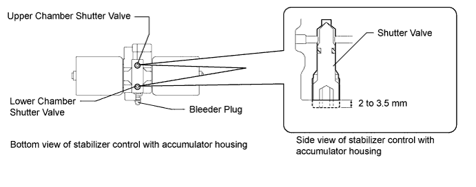
Using a 5 mm hexagon socket wrench, loosen the lower and upper chamber shutter valves of the stabilizer control with accumulator housing 2.0 to 3.5 turns.
- NOTICE:
- When loosening a shutter valve, make sure that the end protrudes 2 to 3.5 mm (0.0787 to 0.137 in.) from the surface of the block, and do not turn the shutter valve any further.
- Do not remove the shutter valves.
- When loosening a shutter valve, make sure that the end protrudes 2 to 3.5 mm (0.0787 to 0.137 in.) from the surface of the block, and do not turn the shutter valve any further.
| 3. REMOVE REAR WHEEL LH |
| 4. DRAIN BRAKE FLUID |
- NOTICE:
- Wash off brake fluid immediately if it comes in contact with any painted surface.
| 5. DISCONNECT REAR BRAKE FLEXIBLE HOSE |
Disconnect the brake tube from the flexible hose with SST while holding the flexible hose with a wrench.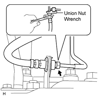
- NOTICE:
- Do not bend or damage the brake tube.
- Do not allow any foreign matter such as dirt and dust to enter the brake tube from the connecting point.
- Do not bend or damage the brake tube.
Remove the clip.
| 6. DISCONNECT REAR DISC BRAKE CYLINDER ASSEMBLY LH |
Remove the 2 bolts and disconnect the rear disc brake cylinder.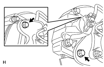
- NOTICE:
- Do not twist or bend the flexible hose.
- Do not disconnect the flexible hose from the disc brake cylinder.
- Do not twist or bend the flexible hose.
| 7. REMOVE REAR DISC LH |
Put matchmarks on the rear disc and axle hub if planning to reuse the disc.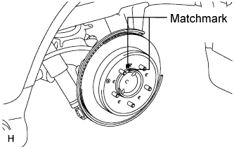
Turn the shoe adjuster as shown in the illustration until the disc turns freely, and then remove the disc.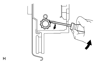
| 8. REMOVE PARKING BRAKE SHOE RETURN TENSION SPRING LH |
Using SST, remove the return spring.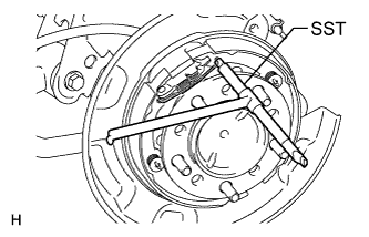
- SST
- 09703-30011
| 9. REMOVE NO. 1 PARKING BRAKE SHOE ASSEMBLY LH |
Using SST, remove the shoe hold down spring cup, compression spring and shoe hold down spring pin.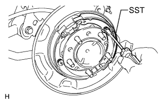
- SST
- 09718-00011
Disconnect the tension spring from the No. 1 parking brake shoe.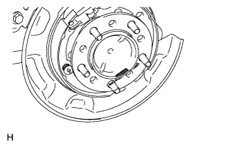
Remove the No. 1 parking brake shoe and shoe adjuster screw set.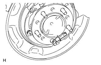
| 10. REMOVE NO. 2 PARKING BRAKE SHOE ASSEMBLY LH |
Using SST, remove the shoe hold down spring cup, compression spring and shoe hold down spring pin.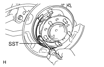
- SST
- 09718-00011
Remove the No. 2 parking brake shoe.
| 11. REMOVE PARKING BRAKE SHOE LEVER SUB-ASSEMBLY LH |
Disconnect the No. 3 parking brake cable from the parking brake shoe lever.
Remove the parking brake shoe lever.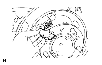
| 12. DISCONNECT NO. 3 PARKING BRAKE CABLE ASSEMBLY |
Remove the bolt and No. 3 parking brake cable.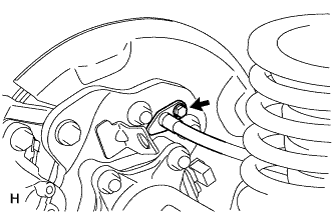
| 13. DISCONNECT REAR SPEED SENSOR LH |
Remove the nut and speed sensor.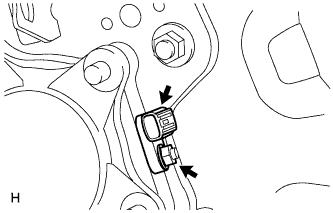
- NOTICE:
- Pull out the sensor while trying as much as possible not to rotate it.
| 14. REMOVE REAR AXLE SHAFT LH |
Remove the 4 nuts and rear axle shaft together with the parking brake plate.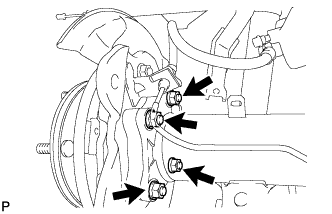
Remove the O-ring.
| 15. REMOVE REAR AXLE SHAFT OIL SEAL LH |
Using SST, tap out the oil seal.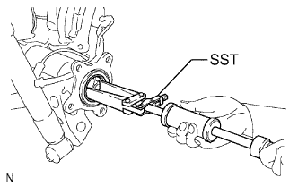
- SST
- 09308-00010
- NOTICE:
- Be careful not to damage the axle housing hole.