INSTALLATION
Removal / installation · Vehicles built Sep 2011 – Dec 2011
| 1.
INSTALL GENERATOR ASSEMBLY |
 |
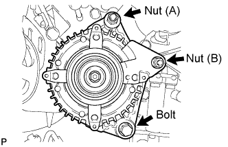
- Install the generator with the bolt and 2 nuts.
-
Torque:
- for bolt and nut (A):
- 39 N*m{
398 kgf*cm
, 29 ft.*lbf
}
- for nut (B):
- 16 N*m{
158 kgf*cm
, 11 ft.*lbf
}
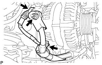
- Connect the generator connector.
Connect the generator wire with the nut.
-
Torque:
- 9.8 N*m{
100 kgf*cm
, 87 in.*lbf
}
Install the terminal cap.
Connect the harness bracket to the generator with the bolt.
-
Torque:
- 8.0 N*m{
82 kgf*cm
, 71 in.*lbf
}
| 2.
CONNECT VANE PUMP ASSEMBLY
|
|
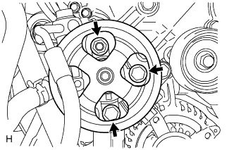
- Connect the vane pump with the 2 bolts and nut.
-
Torque:
- 21 N*m{
214 kgf*cm
, 15 ft.*lbf
}
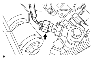
- Connect the connector.
| 3.
INSTALL FAN & GENERATOR V BELT
|
|
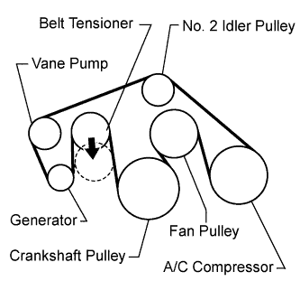
- Set the V belt onto every part except the belt tensioner, as shown in the illustration.
Loosen the V belt by turning the belt tensioner counterclockwise.
Set the V belt to the belt tensioner.
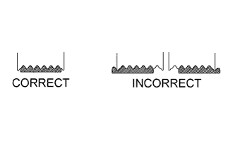
- Check that the belt fits properly in the ribbed grooves.
- HINT:
- Make sure to check by hand that the belt has not slipped out of the grooves on the bottom of the pulley.
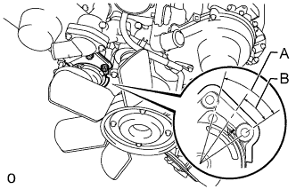
- Check that the arrow on the belt tensioner is within area "A".
If the arrow is outside area "A", replace the fan and generator V belt.
- HINT:
- When a new belt is installed, the arrow should be within area "B". If not, the fan and generator V belt is not installed correctly.
| 4.
INSTALL AIR CLEANER HOSE ASSEMBLY
|
|
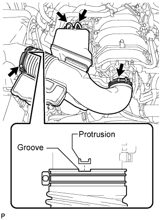
- Install the air cleaner hose so that the protrusion of the air cleaner cap aligns with the groove of the hose as shown in the illustration.
Tighten the 2 clamps.
-
Torque:
- 5.0 N*m{
51 kgf*cm
, 44 in.*lbf
}
Connect the vacuum transmitting hose.
Connect the No. 2 ventilation hose.
| 5.
INSTALL FRONT FENDER APRON SEAL FRONT RH
|
|
- Install the fender apron seal with the 3 clips.
| 6.
INSTALL NO. 1 ENGINE UNDER COVER SUB-ASSEMBLY
|
|
- Install the No. 1 engine under cover with the 10 bolts.
-
Torque:
- 29 N*m{
296 kgf*cm
, 21 ft.*lbf
}
| 7.
INSTALL FRONT FENDER SPLASH SHIELD SUB-ASSEMBLY LH
|
|
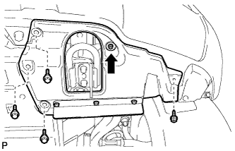
Push in the clip indicated by the arrow in the illustration to install the fender splash shield.
Install the 3 bolts and screw.
| 8.
INSTALL FRONT FENDER SPLASH SHIELD SUB-ASSEMBLY RH
|
|
- HINT:
- Use the same procedures described for the LH side.
| 9.
CONNECT CABLE TO NEGATIVE BATTERY TERMINAL |
|
- NOTICE:
- When disconnecting the cable, some systems need to be initialized after the cable is reconnected (Click here).