INSTALLATION
Removal / installation · Vehicles built Sep 2011 – Dec 2011
Versions by build date: Sep 2011 – Dec 2011 from Jan 2012
| 1. INSTALL VANE PUMP ASSEMBLY |

Install the vane pump with the 2 bolts.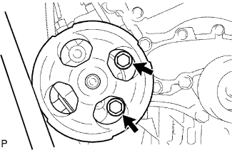

- Torque:
- 21 N*m{ 214 kgf*cm , 15 ft.*lbf }
| 2. CONNECT PRESSURE FEED TUBE |
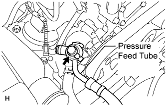 |
Install a new gasket to the pressure feed tube.
Connect the pressure feed tube and install the union bolt.
- Torque:
- 50 N*m{ 510 kgf*cm , 37 ft.*lbf }
| 3. CONNECT NO. 1 OIL RESERVOIR TO PUMP HOSE |
Connect the No.1 oil reservoir to pump hose to the vane pump assembly with the clip.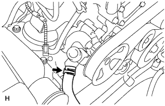
| 4. CONNECT POWER STEERING OIL PRESSURE SWITCH CONNECTOR |
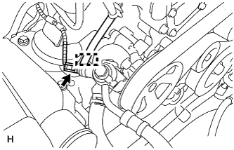 |
Connect the connector.
Attach the wire harness clamp to the bracket.
| 5. INSTALL FAN & GENERATOR V BELT |
While turning the belt tensioner counterclockwise, align the holes, and then insert a bar of φ6 mm (0.236 in.) into the holes to fix the belt tensioner in place.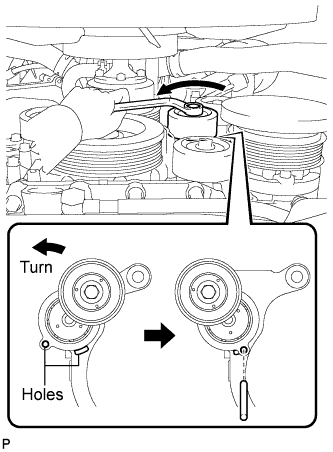
Install the fan and generator V belt.
- HINT:
-
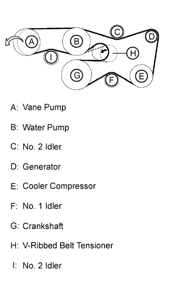
- If it is hard to install the fan and generator V belt, perform the following procedures.
- Put the fan and generator V belt on all parts except the vane pump, as shown in the illustration.
- While releasing the belt tension by turning the belt tensioner counterclockwise, put the fan and generator V belt on the vane pump.
- Put the fan and generator V belt on all parts except the vane pump, as shown in the illustration.
While turning the belt tensioner counterclockwise, remove the bar.
| 6. INSTALL V-BANK COVER SUB-ASSEMBLY |
Install the V-bank cover with the 2 cap nuts.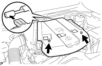
- Torque:
- 7.5 N*m{ 76 kgf*cm , 66 in.*lbf }
| 7. INSTALL FRONT WHEEL RH |
| 8. ADD POWER STEERING FLUID |
| 9. BLEED POWER STEERING FLUID |
Check the fluid level.
Jack up the front of the vehicle and support it with stands.
Turn the steering wheel.
With the engine stopped, turn the wheel slowly from lock to lock several times.
Lower the vehicle.
Start the engine.
Idle the engine for a few minutes.
Turn the steering wheel.
With the engine idling, turn the wheel left or right to the full lock position and keep it there for 2 to 3 seconds, then turn the wheel to the opposite full lock position and keep it there for 2 to 3 seconds. *1
Repeat *1 several times.
- NOTICE:
- For vehicles with VGRS, if the steering wheel is turned from lock to lock repeatedly, the system may stop operating and the amount of rotation before the steering wheel locks may increase due to operation of the overheating prevention function. When the system temperature drops, the system operation automatically returns to normal.
Stop the engine.
Check for foaming or emulsification.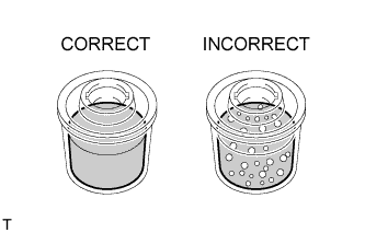
If the system has to be bled twice because of foaming or emulsification, check for fluid leaks in the system.
Check the fluid level.
| 10. INSPECT FOR POWER STEERING FLUID LEAK |
| 11. CONNECT CABLE TO NEGATIVE BATTERY TERMINAL |
- NOTICE:
- When disconnecting the cable, some systems need to be initialized after the cable is reconnected (Click here).