B1497/97 BUS IC Communication Malfunction
Diagnostic trouble codes · Vehicles built Sep 2011 – Dec 2011
Versions by build date: Sep 2011 – Dec 2011 from Jan 2012
DESCRIPTION
The air conditioning harness assembly connects the air conditioning amplifier assembly and each servo motor. The air conditioning amplifier assembly supplies power and sends operation instructions to each servo motor through the air conditioning harness assembly. Each servo motor sends the damper position information to the air conditioning amplifier assembly.| DTC Code |
DTC Detection Condition |
Trouble Area |
| B1497/97 |
An open or error in the communication line. |
|
WIRING DIAGRAM
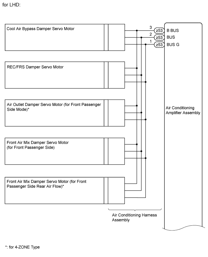

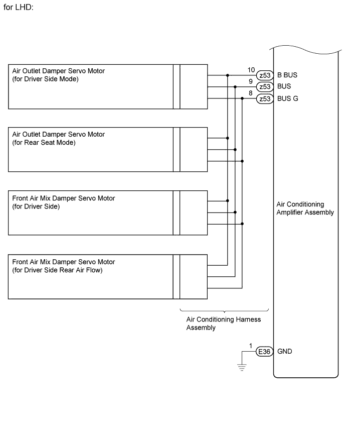
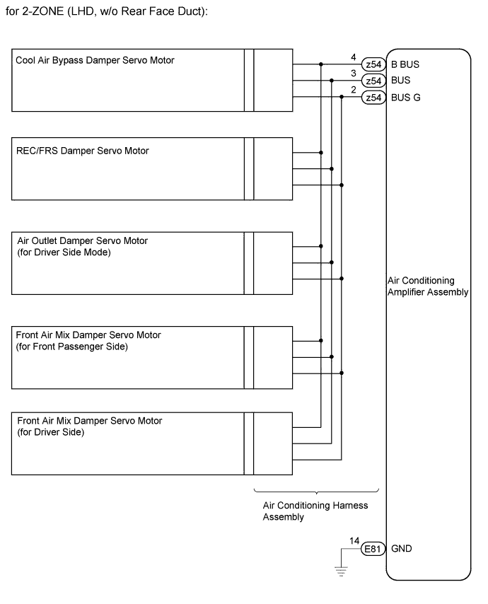
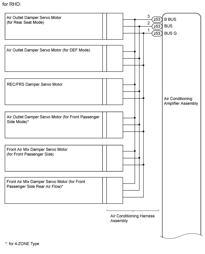
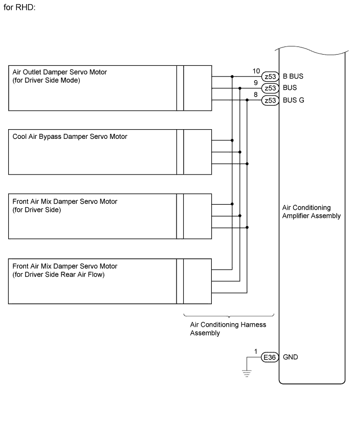
INSPECTION PROCEDURE
| 1. CHECK AIR CONDITIONING AMPLIFIER ASSEMBLY |

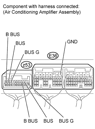 |
w/ Rear Heater
Remove the air conditioning amplifier assembly with its connectors still connected (Click here).
Measure the resistance according to the value(s) in the table below.
- Standard Resistance:
Tester Connection
Condition
Specified Condition
E36-1 (GND) - z53-1 (BUS G)
Always
Below 1 Ω
E36-1 (GND) - z53-8 (BUS G)
z53-1 (BUS G) - Body ground
z53-8 (BUS G) - Body ground
Measure the voltage according to the value(s) in the table below.
- Standard Voltage:
Tester Connection
Condition
Specified Condition
z53-1 (BUS G) - z53-3 (B BUS)
Always
11 to 14 V
z53-8 (BUS G) - z53-10 (B BUS)
Always
11 to 14 V
z53-1 (BUS G) - z53-2 (BUS)
Engine switch on (IG)
Pulse generation
z53-8 (BUS G) - z53-9 (BUS)
w/o Rear Heater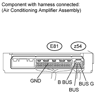
Remove the air conditioning amplifier assembly with its connectors still connected (Click here).
Measure the resistance according to the value(s) in the table below.
- Standard Resistance:
Tester Connection
Condition
Specified Condition
E81-14 (GND) - z54-2 (BUS G)
Always
Below 1 Ω
z54-2 (BUS G) - Body ground
Measure the voltage according to the value(s) in the table below.
Tester Connection
Condition
Specified Condition
z54-2 (BUS G) - z54-4 (B BUS)
Always
11 to 14 V
z54-2 (BUS G) - z54-3 (BUS)
Engine switch on (IG)
Pulse generation
Result Result
Proceed to
OK (for LHD)
A
OK (for RHD)
B
NG
C
|
|
||||
|
|
||||

| A | ||
 |
||
| ||