U1110 Lost Communication with Clearance Sonar Module
Diagnostic trouble codes · Vehicles built Sep 2011 – Dec 2011
Versions by build date: Sep 2011 – Dec 2011 from Jan 2012
DESCRIPTION
| DTC Code |
DTC Detection Condition |
Trouble Area |
| U1110 |
There is no communication from the clearance warning ECU. |
|
- HINT:
- For vehicles with the TOYOTA parking assist-sensor system only.
WIRING DIAGRAM
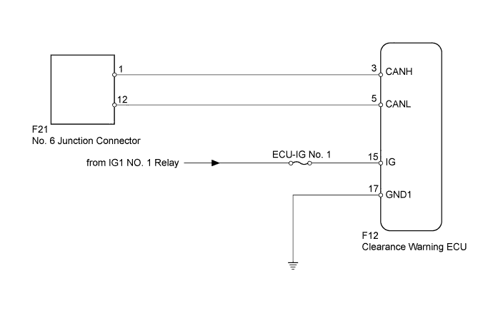

INSPECTION PROCEDURE
| 1. DISCONNECT CABLE FROM NEGATIVE BATTERY TERMINAL |

Disconnect the cable from the negative (-) battery terminal before measuring the resistances of the main wire and the branch wire.
- CAUTION:
- For vehicles with an SRS system:
- Wait at least 90 seconds after disconnecting the cable from the negative (-) battery terminal to disable the SRS system.
- NOTICE:
- When disconnecting the cable, some systems need to be initialized after the cable is reconnected (Click here).
| NEXT | |
 |
| 2. CHECK FOR OPEN IN CAN BUS WIRE (CLEARANCE WARNING ECU BRANCH WIRE) |
Disconnect the F12 clearance warning ECU connector.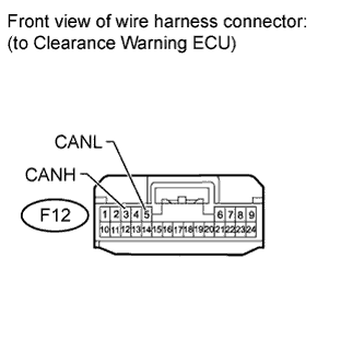
Measure the resistance according to the value(s) in the table below.
- Standard Resistance:
Tester Connection
Switch Condition
Specified Condition
F12-3 (CANH) - F12-5 (CANL)
Ignition switch off
54 to 69 Ω
|
|
||||

| OK | |
|
| 3. CHECK HARNESS AND CONNECTOR (CLEARANCE WARNING ECU - BATTERY AND BODY GROUND) |
Connect the cable to the negative (-) battery terminal.
- NOTICE:
- When disconnecting the cable, some systems need to be initialized after the cable is reconnected (Click here).
Disconnect the F12 clearance warning ECU connector.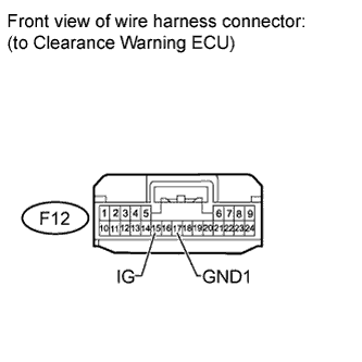
Measure the resistance according to the value(s) in the table below.
- Standard Resistance:
Tester Connection
Condition
Specified Condition
F12-17 (GND1) - Body ground
Always
Below 1 Ω
Measure the voltage according to the value(s) in the table below.
- Standard Voltage:
Tester Connection
Switch Condition
Specified Condition
F12-15 (IG) - Body ground
Ignition switch ON
11 to 14 V
|
|
||||
| OK | ||
 |
||
| ||